2019 DODGE CHALLENGER clock
[x] Cancel search: clockPage 62 of 532

EXTERIOR LIGHTS
Headlight Switch
The headlight switch is located on the left side of the
instrument panel. This switch controls the operation of the
headlights, parking lights, instrument panel lights, instru-
ment panel light dimming, interior lights and fog lights.
Rotate the headlight switch clockwise to the first detent for
parking light and instrument panel light operation. Rotate
the headlight switch to the second detent for headlight,
parking light and instrument panel light operation. Push
the switch to enable fog lights (if equipped).
Multifunction Lever
The multifunction lever controls the operation of the turn
signals, headlight beam selection and passing lights. The
multifunction lever is located on the left side of the steering
column.
Daytime Running Lights (DRL) — If Equipped
The Daytime Running Lights will turn on when the engine
is started and will remain on unless the headlamps are
turned to the on position, the parking brake is applied, or
the engine is shut OFF.
Headlight Switch
Multifunction Lever
60 GETTING TO KNOW YOUR VEHICLE
Page 63 of 532

NOTE:If allowed by law in the country in which the
vehicle was purchased, the Daytime Running Lights can be
turned on and off using the Uconnect System, refer to
“Uconnect Settings” in “Multimedia” for further informa-
tion.
High/Low Beam Switch
Push the multifunction lever away from you to switch the
headlights to high beam. Pull the multifunction lever
toward you to switch the headlights back to low beam.
Automatic High Beam Headlamp Control — If
Equipped
The Automatic High Beam Headlamp Control system
provides increased forward lighting at night by automat-
ing high beam control through the use of a digital camera
mounted on the windshield. This camera detects vehicle
specific light and automatically switches from high beams
to low beams until the approaching vehicle is out of view.
NOTE:
• The Automatic High Beam Headlamp Control can be
turned on or off using the Uconnect System. Refer to
“Uconnect Settings” in “Multimedia” for further infor-
mation. •
Broken, muddy, or obstructed headlights and taillights
of vehicles in the field of view will cause headlights to
remain on longer (closer to the vehicle). Also, dirt, film,
and other obstructions on the windshield or camera lens
will cause the system to function improperly.
If the windshield or Automatic High Beam Headlamp
Control mirror is replaced, the mirror must be re-aimed to
ensure proper performance. See your local authorized
dealer.
Flash-To-Pass
You can signal another vehicle with your headlights by
lightly pulling the multifunction lever toward you. This
will turn on the high beam headlights until the lever is
released.
NOTE: If the multifunction lever is held in the flash-to pass
position for more than 20 seconds, the high beams will shut
off.
Automatic Headlights
This system automatically turns the headlights on or off
according to ambient light levels. To turn the system on,
rotate the headlight switch counterclockwise to the AUTO
position. When the system is on, the headlight time delay
feature is also on. This means the headlights will stay on
3
GETTING TO KNOW YOUR VEHICLE 61
Page 75 of 532

IconDescription
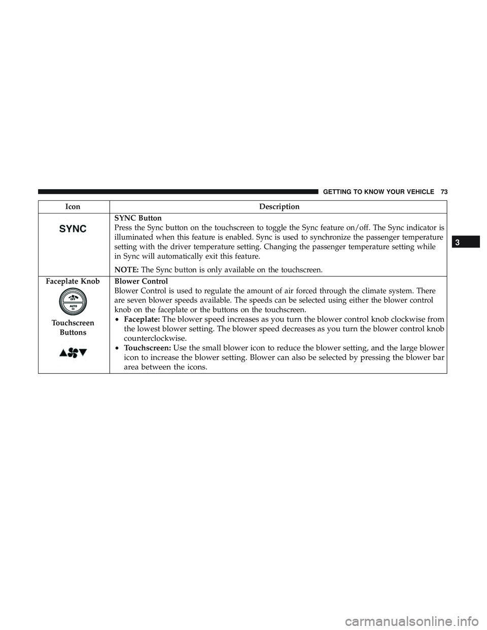
SYNC Button
Press the Sync button on the touchscreen to toggle the Sync feature on/off. The Sync indicator is
illuminated when this feature is enabled. Sync is used to synchronize the passenger temperature
setting with the driver temperature setting. Changing the passenger temperature setting while
in Sync will automatically exit this feature.
NOTE:The Sync button is only available on the touchscreen.
Faceplate Knob
Touchscreen Buttons
Blower Control
Blower Control is used to regulate the amount of air forced through the climate system. There
are seven blower speeds available. The speeds can be selected using either the blower control
knob on the faceplate or the buttons on the touchscreen.
• Faceplate: The blower speed increases as you turn the blower control knob clockwise from
the lowest blower setting. The blower speed decreases as you turn the blower control knob
counterclockwise.
• Touchscreen: Use the small blower icon to reduce the blower setting, and the large blower
icon to increase the blower setting. Blower can also be selected by pressing the blower bar
area between the icons. 3
GETTING TO KNOW YOUR VEHICLE 73
Page 290 of 532

Bulb Number
Rear Side Marker LED (Serviced At Authorized Dealer)
Backup Lamp LED (Serviced At Authorized Dealer)
Center High-Mount Stop Lamp (CHMSL) LED (Serviced At Authorized Dealer)
License LED (Serviced At Authorized Dealer)
* The headlamps are a type of high-voltage discharge tube.
High voltage can remain in the circuit even with the
headlamp switch off and the key removed. Because of this,
you should not attempt to service a headlamp bulb your-
self. If a headlamp bulb fails, take your vehicle to an
authorized dealer for service.
Replacing Exterior Bulbs
Low Beam Headlamp, High Beam Headlamp —
Models With Halogen Headlamps — If Equipped
To replace the passenger side lamps:
1. Open the hood.
2. Remove the trim panel to access the headlamp assembly.
3. Reach behind the passenger headlamp assembly.
NOTE: The park/turn lamps can also be accessed at this
point. 4. Turn the headlamp access cap counterclockwise to re-
move.
5. Remove bulb by turning it counter clockwise and dis- connect.
6. Install new bulb by turning it clockwise and reconnect.
7. Reinstall headlamp access cap by turning it clockwise and then reinstall headlamp cover.
To replace the driver side lamps:
1. Open the hood.
2. Remove the air cleaner filter cover by removing three fasteners and loosening the clean air inlet clamp and
then rotate cover off to the side.
NOTE: The cover has an electrical connector that does not
need to be disconnected if the cover is rotated off to the
side.
288 IN CASE OF EMERGENCY
Page 291 of 532

3. Remove one fastener on the lower air box to remove andaccess the rear of the headlamp assembly.
4. Reach behind the passenger headlamp assembly.
5. Remove the headlamp cover.
6. Turn the headlamp access cap counterclockwise to re- move.
7. Remove bulb by turn it counter clockwise and discon- nect.
8. Install new bulb by turning it clockwise and reconnect.
9. Reinstall headlamp access cap by turning it clockwise and then reinstall headlamp cover.
10. Reinstall engine air cleaner assembly.
Low Beam Headlamp, High Beam Headlamp —
Models With High Intensity Discharge (HID)
Headlamps — If Equipped
The headlamps are a type of high voltage discharge tube.
High voltage can remain in the circuit even with the
headlamp switch off and the key removed. Because of this,
you should not attempt to service a headlamp bulb
yourself. If a headlamp bulb fails, take your vehicle to an
authorized dealer for service.
WARNING!
A transient high voltage occurs at the bulb sockets of
HID headlamps when the headlamp switch is turned
ON. It may cause serious electrical shock or electrocu-
tion if not serviced properly. See your authorized
dealer for service.
NOTE: On vehicles equipped with HID headlamps, when
the headlamps are turned on, there is a blue hue to the
lamps. This diminishes and becomes more white after
approximately ten seconds, as the system charges.
Front Park/Signature Lamp
The Front Park/Signature function is part of the headlamp
assembly and use LED lamps that are not serviceable
separately. The headlamps must be replaced as an assem-
bly, see your authorized dealer.
Front Turn/DRL Lamp
The Front Turn/DRL function is part of the headlamp
assembly and use LED lamps that are not serviceable
separately. The headlamps must be replaced as an assem-
bly, see your authorized dealer.
7
IN CASE OF EMERGENCY 289
Page 300 of 532

CavityCartridge Fuse Mini-FuseDescription
(300) – If Equipped
34 – 10 Amp RedSteering Column Module/Clock
(300)
35 – 5 Amp TanBattery Sensor
36 – 15 Amp BlueElectronic Exhaust Valve – If
Equipped
37 – 20 Amp YellowRadio
38 – 20 Amp YellowPower Outlet Inside Arm Rest/
Console Media Hub
40 30 Amp Pink –Fuel Pump (6.2L SRT HO – If
Equipped)
41 30 Amp Pink –Fuel Pump (6.2L SRT HO – If
Equipped)
42 30 Amp Pink –Rear Defrost
43 – 20 Amp YellowComfort Seat And Steering
Wheel Module (Heated Steering
Wheel/RR Heated Seats)
44 – 10 Amp RedPark Assist / Blind Spot / Rear
View Camera
298 IN CASE OF EMERGENCY
Page 303 of 532

JACKING AND TIRE CHANGING
WARNING!
•Do not attempt to change a tire on the side of the
vehicle close to moving traffic. Pull far enough off
the road to avoid the danger of being hit when
operating the jack or changing the wheel.
• Being under a jacked-up vehicle is dangerous. The
vehicle could slip off the jack and fall on you. You
could be crushed. Never put any part of your body
under a vehicle that is on a jack. If you need to get
under a raised vehicle, take it to a service center
where it can be raised on a lift.
• Never start or run the engine while the vehicle is on
a jack.
• The jack is designed to be used as a tool for changing
tires only. The jack should not be used to lift the
vehicle for service purposes. The vehicle should be
jacked on a firm level surface only. Avoid ice or
slippery areas.
Jack Location/Spare Tire Stowage
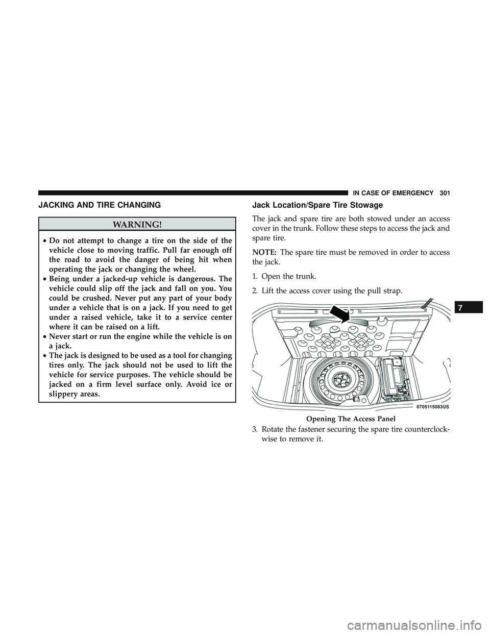
The jack and spare tire are both stowed under an access
cover in the trunk. Follow these steps to access the jack and
spare tire.
NOTE: The spare tire must be removed in order to access
the jack.
1. Open the trunk.
2. Lift the access cover using the pull strap.
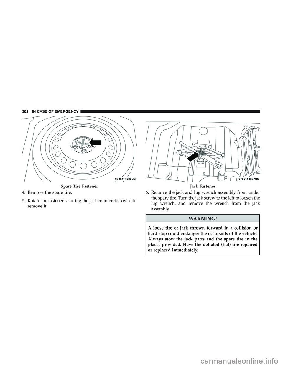
3. Rotate the fastener securing the spare tire counterclock- wise to remove it.
Opening The Access Panel
7
IN CASE OF EMERGENCY 301
Page 304 of 532

4. Remove the spare tire.
5. Rotate the fastener securing the jack counterclockwise toremove it. 6. Remove the jack and lug wrench assembly from under
the spare tire. Turn the jack screw to the left to loosen the
lug wrench, and remove the wrench from the jack
assembly.
WARNING!
A loose tire or jack thrown forward in a collision or
hard stop could endanger the occupants of the vehicle.
Always stow the jack parts and the spare tire in the
places provided. Have the deflated (flat) tire repaired
or replaced immediately.
Spare Tire FastenerJack Fastener
302 IN CASE OF EMERGENCY