2019 CHRYSLER 300 warning
[x] Cancel search: warningPage 123 of 492
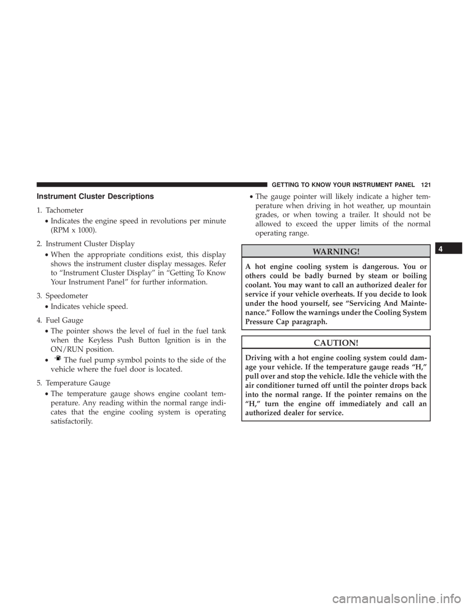
Instrument Cluster Descriptions
1. Tachometer•Indicates the engine speed in revolutions per minute
(RPM x 1000).
2. Instrument Cluster Display •When the appropriate conditions exist, this display
shows the instrument cluster display messages. Refer
to “Instrument Cluster Display” in “Getting To Know
Your Instrument Panel” for further information.
3. Speedometer •Indicates vehicle speed.
4. Fuel Gauge •The pointer shows the level of fuel in the fuel tank
when the Keyless Push Button Ignition is in the
ON/RUN position.
•
The fuel pump symbol points to the side of the
vehicle where the fuel door is located.
5. Temperature Gauge
•The temperature gauge shows engine coolant tem-
perature. Any reading within the normal range indi-
cates that the engine cooling system is operating
satisfactorily. •
The gauge pointer will likely indicate a higher tem-
perature when driving in hot weather, up mountain
grades, or when towing a trailer. It should not be
allowed to exceed the upper limits of the normal
operating range.
WARNING!
A hot engine cooling system is dangerous. You or
others could be badly burned by steam or boiling
coolant. You may want to call an authorized dealer for
service if your vehicle overheats. If you decide to look
under the hood yourself, see “Servicing And Mainte-
nance.” Follow the warnings under the Cooling System
Pressure Cap paragraph.
CAUTION!
Driving with a hot engine cooling system could dam-
age your vehicle. If the temperature gauge reads “H,”
pull over and stop the vehicle. Idle the vehicle with the
air conditioner turned off until the pointer drops back
into the normal range. If the pointer remains on the
“H,” turn the engine off immediately and call an
authorized dealer for service.
4
GETTING TO KNOW YOUR INSTRUMENT PANEL 121
Page 124 of 492
NOTE:The hard telltales will illuminate for a bulb check
when the ignition is first cycled.
INSTRUMENT CLUSTER DISPLAY
Your vehicle will be equipped with an instrument cluster
display, which offers useful information to the driver. With
the ignition in the STOP/OFF mode, opening/closing of a
door will activate the display for viewing, and display the
total miles, or kilometers, in the odometer. Your instrument
cluster display is designed to display important informa-
tion about your vehicle’s systems and features. Using a
driver interactive display located on the instrument panel,
your instrument cluster display can show you how sys-
tems are working and give you warnings when they are
not. The steering wheel mounted controls allow you to
scroll through the main menus and submenus. You can
access the specific information you want and make selec-
tions and adjustments.
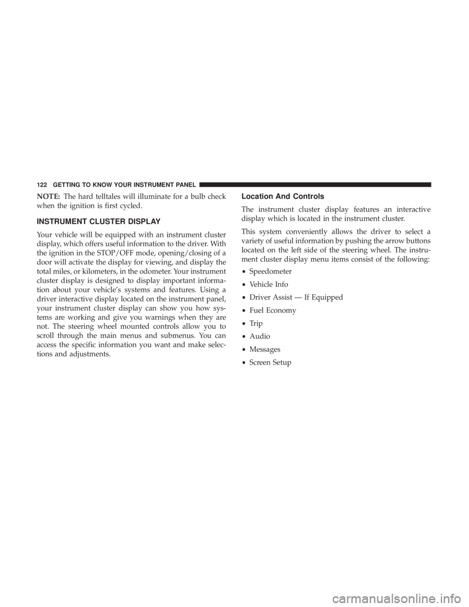
Location And Controls
The instrument cluster display features an interactive
display which is located in the instrument cluster.
This system conveniently allows the driver to select a
variety of useful information by pushing the arrow buttons
located on the left side of the steering wheel. The instru-
ment cluster display menu items consist of the following:
• Speedometer
• Vehicle Info
• Driver Assist — If Equipped
• Fuel Economy
• Trip
• Audio
• Messages
• Screen Setup
122 GETTING TO KNOW YOUR INSTRUMENT PANEL
Page 128 of 492
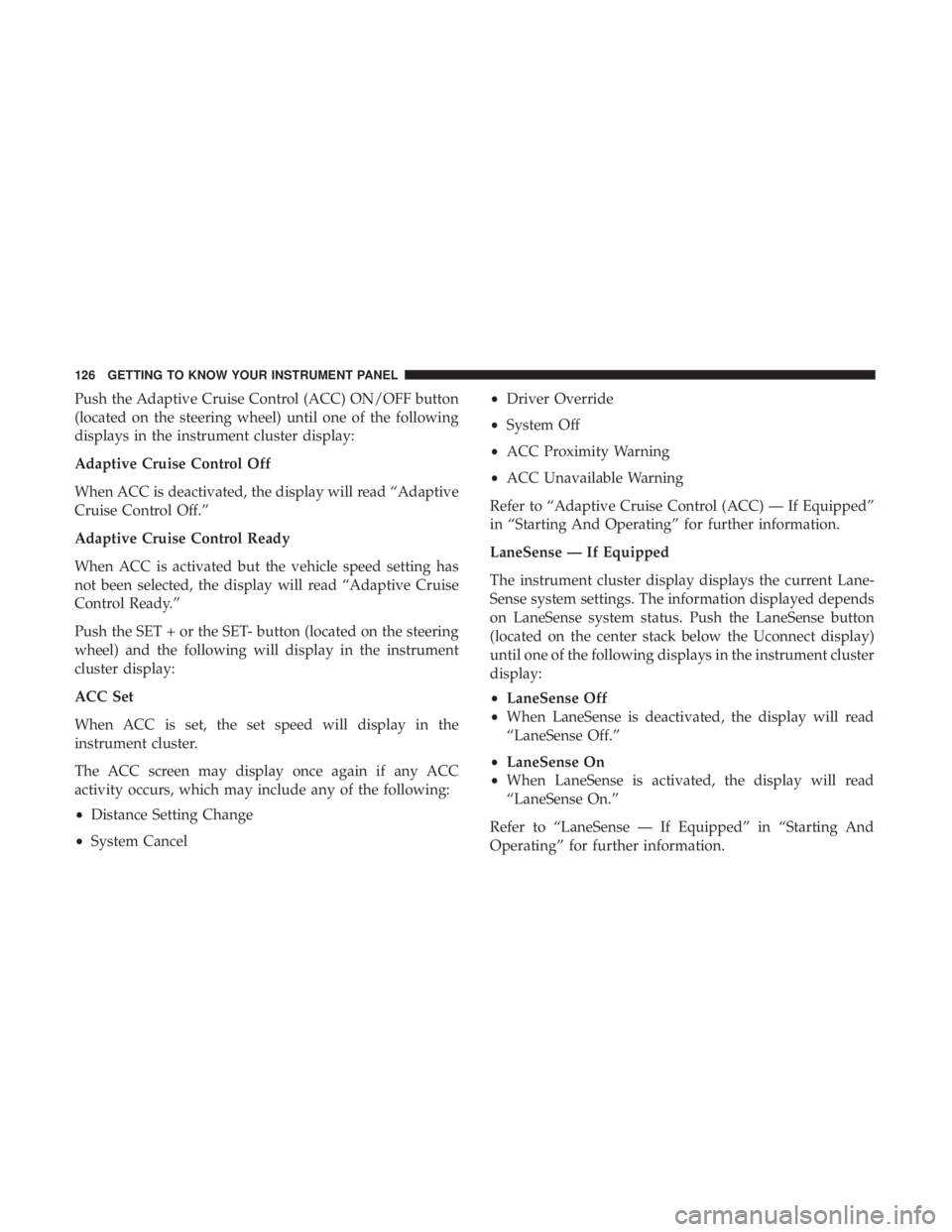
Push the Adaptive Cruise Control (ACC) ON/OFF button
(located on the steering wheel) until one of the following
displays in the instrument cluster display:
Adaptive Cruise Control Off
When ACC is deactivated, the display will read “Adaptive
Cruise Control Off.”
Adaptive Cruise Control Ready
When ACC is activated but the vehicle speed setting has
not been selected, the display will read “Adaptive Cruise
Control Ready.”
Push the SET + or the SET- button (located on the steering
wheel) and the following will display in the instrument
cluster display:
ACC Set
When ACC is set, the set speed will display in the
instrument cluster.
The ACC screen may display once again if any ACC
activity occurs, which may include any of the following:
•Distance Setting Change
• System Cancel •
Driver Override
• System Off
• ACC Proximity Warning
• ACC Unavailable Warning
Refer to “Adaptive Cruise Control (ACC) — If Equipped”
in “Starting And Operating” for further information.
LaneSense — If Equipped
The instrument cluster display displays the current Lane-
Sense system settings. The information displayed depends
on LaneSense system status. Push the LaneSense button
(located on the center stack below the Uconnect display)
until one of the following displays in the instrument cluster
display:
• LaneSense Off
• When LaneSense is deactivated, the display will read
“LaneSense Off.”
• LaneSense On
• When LaneSense is activated, the display will read
“LaneSense On.”
Refer to “LaneSense — If Equipped” in “Starting And
Operating” for further information.
126 GETTING TO KNOW YOUR INSTRUMENT PANEL
Page 129 of 492
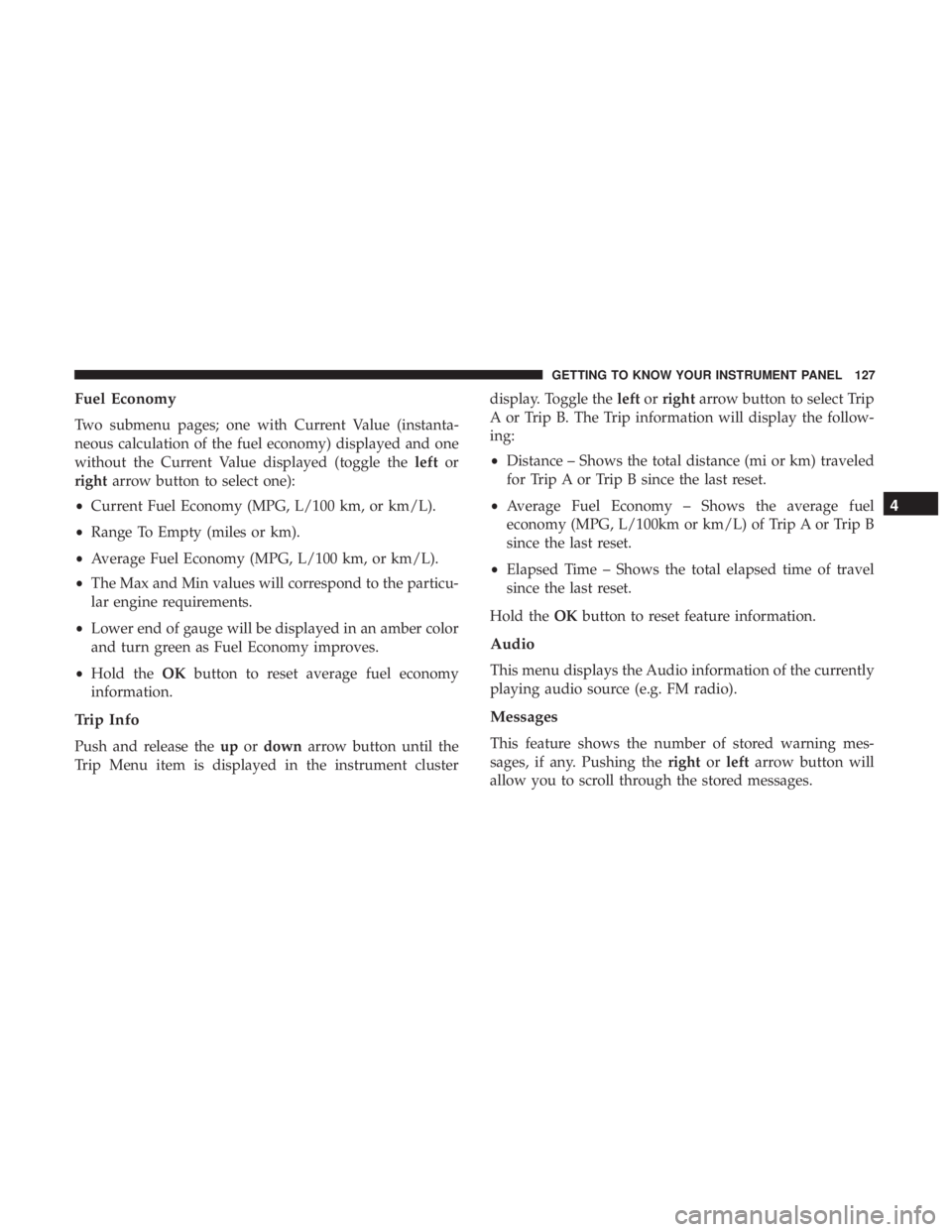
Fuel Economy
Two submenu pages; one with Current Value (instanta-
neous calculation of the fuel economy) displayed and one
without the Current Value displayed (toggle theleftor
right arrow button to select one):
• Current Fuel Economy (MPG, L/100 km, or km/L).
• Range To Empty (miles or km).
• Average Fuel Economy (MPG, L/100 km, or km/L).
• The Max and Min values will correspond to the particu-
lar engine requirements.
• Lower end of gauge will be displayed in an amber color
and turn green as Fuel Economy improves.
• Hold the OKbutton to reset average fuel economy
information.
Trip Info
Push and release the upordown arrow button until the
Trip Menu item is displayed in the instrument cluster display. Toggle the
leftorright arrow button to select Trip
A or Trip B. The Trip information will display the follow-
ing:
• Distance – Shows the total distance (mi or km) traveled
for Trip A or Trip B since the last reset.
• Average Fuel Economy – Shows the average fuel
economy (MPG, L/100km or km/L) of Trip A or Trip B
since the last reset.
• Elapsed Time – Shows the total elapsed time of travel
since the last reset.
Hold the OKbutton to reset feature information.
Audio
This menu displays the Audio information of the currently
playing audio source (e.g. FM radio).
Messages
This feature shows the number of stored warning mes-
sages, if any. Pushing the rightorleft arrow button will
allow you to scroll through the stored messages.
4
GETTING TO KNOW YOUR INSTRUMENT PANEL 127
Page 131 of 492
5. Odometer•Show (default)
• Hide
6. Fuel Gauge •Standard (default)
• Detailed
7. Restore Default •Ok
• Cancel
Battery Saver On/Battery Saver Mode Message —
Electrical Load Reduction Actions — If Equipped
This vehicle is equipped with an Intelligent Battery Sensor
(IBS) to perform additional monitoring of the electrical
system and status of the vehicle battery.
In cases when the IBS detects charging system failure, or
the vehicle battery conditions are deteriorating, electrical
load reduction actions will take place to extend the driving
time and distance of the vehicle. This is done by reducing
power to or turning off non-essential electrical loads.
Load reduction is only active when the engine is running.
It will display a message if there is a risk of battery depletion to the point where the vehicle may stall due to
lack of electrical supply, or will not restart after the current
drive cycle.
When load reduction is activated, the message “Battery
Saver On” or “Battery Saver Mode” will appear in the
instrument cluster.
These messages indicate the vehicle battery has a low state
of charge and continues to lose electrical charge at a rate
that the charging system cannot sustain.
NOTE:
•
The charging system is independent from load reduc-
tion. The charging system performs a diagnostic on the
charging system continuously.
• If the Battery Charge Warning Light is on it may indicate
a problem with the charging system. Refer to “Battery
Charge Warning Light” in “Getting To Know Your
Instrument Panel” for further information.
The electrical loads that may be switched off (if equipped),
and vehicle functions which can be affected by load
reduction:
• Heated Seat/Vented Seats/Heated Wheel
• Heated/Cooled Cup Holders — If Equipped
4
GETTING TO KNOW YOUR INSTRUMENT PANEL 129
Page 133 of 492
After a trip:
•Check if any aftermarket equipment was installed (ad-
ditional lights, upfitter electrical accessories, audio sys-
tems, alarms) and review specifications if any (load and
Ignition Off Draw currents).
• Evaluate the latest driving cycles (distance, driving time
and parking time).
• The vehicle should have service performed if the mes-
sage is still present during consecutive trips and the
evaluation of the vehicle and driving pattern did not
help to identify the cause.
WARNING LIGHTS AND MESSAGES
The warning/indicator lights will illuminate in the instru-
ment panel together with a dedicated message and/or
acoustic signal when applicable. These indications are
indicative and precautionary and as such must not be
considered as exhaustive. Always refer to the information
in this chapter in the event of a failure indication. All active
telltales will display first if applicable. The system check
menu may appear different based upon equipment options
and current vehicle status. Some telltales are optional and
may not appear.
Red Warning Lights
— Air Bag Warning Light
This warning light will illuminate to indicate a fault with
the air bag, and will turn on for four to eight seconds as a
bulb check when the ignition is placed in the ON/RUN or
ACC/ON/RUN position. This light will illuminate with a
single chime when a fault with the air bag has been
detected, it will stay on until the fault is cleared. If the light
is either not on during startup, stays on, or turns on while
driving, have the system inspected at an authorized dealer
as soon as possible.
— Brake Warning Light
This warning light monitors various brake functions, in-
cluding brake fluid level and parking brake application. If
the brake light turns on it may indicate that the parking
brake is applied, that the brake fluid level is low, or that
there is a problem with the anti-lock brake system reser-
voir.
4
GETTING TO KNOW YOUR INSTRUMENT PANEL 131
Page 134 of 492
If the light remains on when the parking brake has been
disengaged, and the fluid level is at the full mark on the
master cylinder reservoir, it indicates a possible brake
hydraulic system malfunction or that a problem with the
Brake Booster has been detected by the Anti-Lock Brake
System (ABS) / Electronic Stability Control (ESC) system.
In this case, the light will remain on until the condition has
been corrected. If the problem is related to the brake
booster, the ABS pump will run when applying the brake,
and a brake pedal pulsation may be felt during each stop.
The dual brake system provides a reserve braking capacity
in the event of a failure to a portion of the hydraulic
system. A leak in either half of the dual brake system is
indicated by the Brake Warning Light, which will turn on
when the brake fluid level in the master cylinder has
dropped below a specified level.
The light will remain on until the cause is corrected.
NOTE:The light may flash momentarily during sharp
cornering maneuvers, which change fluid level conditions.
The vehicle should have service performed, and the brake
fluid level checked.
If brake failure is indicated, immediate repair is necessary.WARNING!
Driving a vehicle with the red brake light on is
dangerous. Part of the brake system may have failed. It
will take longer to stop the vehicle. You could have a
collision. Have the vehicle checked immediately.
Vehicles equipped with the Anti-Lock Brake System (ABS)
are also equipped with Electronic Brake Force Distribution
(EBD). In the event of an EBD failure, the Brake Warning
Light will turn on along with the ABS Light. Immediate
repair to the ABS system is required.
Operation of the Brake Warning Light can be checked by
turning the ignition switch from the OFF position to the
ON/RUN position. The light should illuminate for ap-
proximately two seconds. The light should then turn off
unless the parking brake is applied or a brake fault is
detected. If the light does not illuminate, have the light
inspected by an authorized dealer.
The light also will turn on when the parking brake is
applied with the ignition switch in the ON/RUN position.
NOTE: This light shows only that the parking brake is
applied. It does not show the degree of brake application.
132 GETTING TO KNOW YOUR INSTRUMENT PANEL
Page 135 of 492
— Battery Charge Warning Light
This warning light will illuminate when the battery is not
charging properly. If it stays on while the engine is run-
ning, there may be a malfunction with the charging system.
Contact an authorized dealer as soon as possible.
This indicates a possible problem with the electrical system
or a related component.
— Door Open Warning Light
This indicator will illuminate when a door is ajar/open and
not fully closed.
NOTE:If the vehicle is moving, there will also be a single
chime.
— Electric Power Steering Fault Warning Light
This warning light will turn on when there’s a fault with
the EPS (Electric Power Steering) system. Refer to “Power
Steering” in “Starting And Operating” for further informa-
tion.
WARNING!
Continued operation with reduced assist could pose a
safety risk to yourself and others. Service should be
obtained as soon as possible.
— Electronic Throttle Control (ETC) Warning
Light
This warning light will illuminate to indicate a problem
with the Electronic Throttle Control (ETC) system. If a
problem is detected while the vehicle is running, the light
will either stay on or flash depending on the nature of the
problem. Cycle the ignition when the vehicle is safely and
completely stopped and the transmission is placed in the
PARK position. The light should turn off. If the light
remains on with the vehicle running, your vehicle will
usually be drivable; however, see an authorized dealer for
service as soon as possible.
NOTE: This light may turn on if the accelerator and brake
pedals are pressed at the same time.
4
GETTING TO KNOW YOUR INSTRUMENT PANEL 133