2019 AUDI TT ROADSTER ignition
[x] Cancel search: ignitionPage 263 of 304

8S58012721BA
Wheels
instrument cluster display along with the mes-
sage Tire pressure: malfunction! See owner's
manual.
If the is indicator light appears after switching
the ignition on or while driving and the @ indi-
cator light also blinks for approximately one mi-
nute and then stays on, there is system malfunc-
tion. The following are examples of situations
that could cause a malfunction:
— If the message appears at the end of the adap-
tation phase, the system may not detect one or
several of the wheel sensors necessary for pres-
sure monitoring. This may result from one or
more wheels without wheel sensors or with in-
compatible wheel sensors being installed.
—Awheel sensor or another component has
failed.
— Using snow chains can affect the function of
the system because of the shielding effect of
the chains.
— The tire pressure monitoring system is not
available due to a malfunction.
— Transmitters with the same frequency, such as
headphones or remote-controlled devices, may
cause a temporary system malfunction due to
the strong electromagnetic field.
The iis indicator light and the message turn off
once the tire pressure monitoring system is avail-
able again. If you cannot correct the malfunction
and the ia indicator light stays on, drive imme-
diately to an authorized Audi dealer or author-
ized Audi Service Facility to have the malfunction
repaired.
261
Page 264 of 304

Care and cleaning
Care and cleaning
General information
Regular, proper care helps to maintain your vehi-
cle's value. It can also be a requirement when
submitting warranty claims for corrosion damage
and paint defects on the body.
The necessary care products can be obtained
from an authorized Audi dealer or authorized Au-
di Service Facility. Read and follow the instruc-
tions for use on the packaging.
ZA\ WARNING
— Using cleaning and care products incorrectly
can be dangerous to your health.
— Always store cleaning and care products out
of reach of children to reduce the risk of poi-
soning.
@ For the sake of the environment
— Purchase environmentally-friendly cleaning
products if possible.
— Do not dispose of cleaning and care prod-
ucts with household trash.
Car washes
The longer that deposits remain on the vehicle,
the more the surface may be damaged. High
temperatures such as those caused by sunlight
increase the damaging effect.
Before washing, rinse off heavy deposits with
plenty of water.
Stubborn deposits such as bird droppings or tree
sap are best removed with plenty of water anda
microfiber cloth.
Also, wash the underside of your vehicle once
road salt stops being used for the season.
Pressure washers
When washing your vehicle with a pressure wash-
er, always follow the operating instructions pro-
vided with the pressure washer. This is especially
important in regard to the pressure and spraying
distance. Do not direct the stream of water di-
rectly onto seals for the side windows, doors, lug-
262
gage compartment lid or hood or onto the tires,
rubber hoses, insulating material, sensors*, or
camera lenses*. Keep a distance of at least 16 in
(40 cm).
Do not remove snow and ice with a pressure
washer.
Never use cone nozzles or high pressure nozzles.
The water temperature must not be above 140 °F
(60 °C).
Automatic car wash
Spray off the vehicle before washing.
Make sure that the windows are closed and the
windshield wipers are off. Follow instructions
from the car wash operator, especially if there are
accessories attached to your vehicle.
If possible, use car washes that do not have
brushes.
Washing by hand
Clean the vehicle starting from the top and work-
ing downward using a soft sponge or cleaning
brush. Use solvent-free cleaning products.
Washing vehicles with matte finish paint by
hand
To reduce the risk of damaging the paint when
washing, first remove dust and large particles
from your vehicle. Insects, grease spots, and fin-
gerprints are best removed with a special cleaner
for matte finish paint.
Apply the product using a microfiber cloth. To re-
duce the risk of damaging the paint surface, do
not use too much pressure.
Rinse the vehicle thoroughly with water. Then
clean using a neutral shampoo and a soft micro-
fiber cloth.
Rinse the vehicle thoroughly again and let it air
dry. Remove any water residue using a chamois.
ZA\ WARNING
—To reduce the risk of accidents, only wash
the vehicle when the ignition is off and fol-
low the instructions from the car wash oper-
ator.
Page 271 of 304

8S8012721BA
Emergency assistance
— The tire sealant must not come in contact
with skin, eyes, or clothing.
— If tire sealant comes into contact with your
eyes or your skin, thoroughly rinse the af-
fected area immediately with clean water.
— Do not inhale the fumes.
— If you swallow any of the tire sealant, thor-
oughly rinse your mouth immediately and
drink a lot of water. Do not induce vomiting.
Seek medical attention immediately.
— Change your clothing immediately if it
comes into contact with tire sealant.
— If an allergic reaction occurs, seek medical
attention immediately.
— Keep the tire sealant away from children.
G) Tips
— If sealant leaks, allow it to dry in place. You
can then peel it off like a sticker.
— Note the expiration date on the sealant bot-
tle. Replace the tire sealant at an authorized
Audi dealer or authorized Audi Service Fa-
cility.
— Radio reception can be interrupted when
operating the compressor.
— Follow the legal regulations that are appli-
cable in the country where you are operating
the vehicle.
Fate ma cry
Applies to: vehicles with tire mobility kit
RAZ-0213]
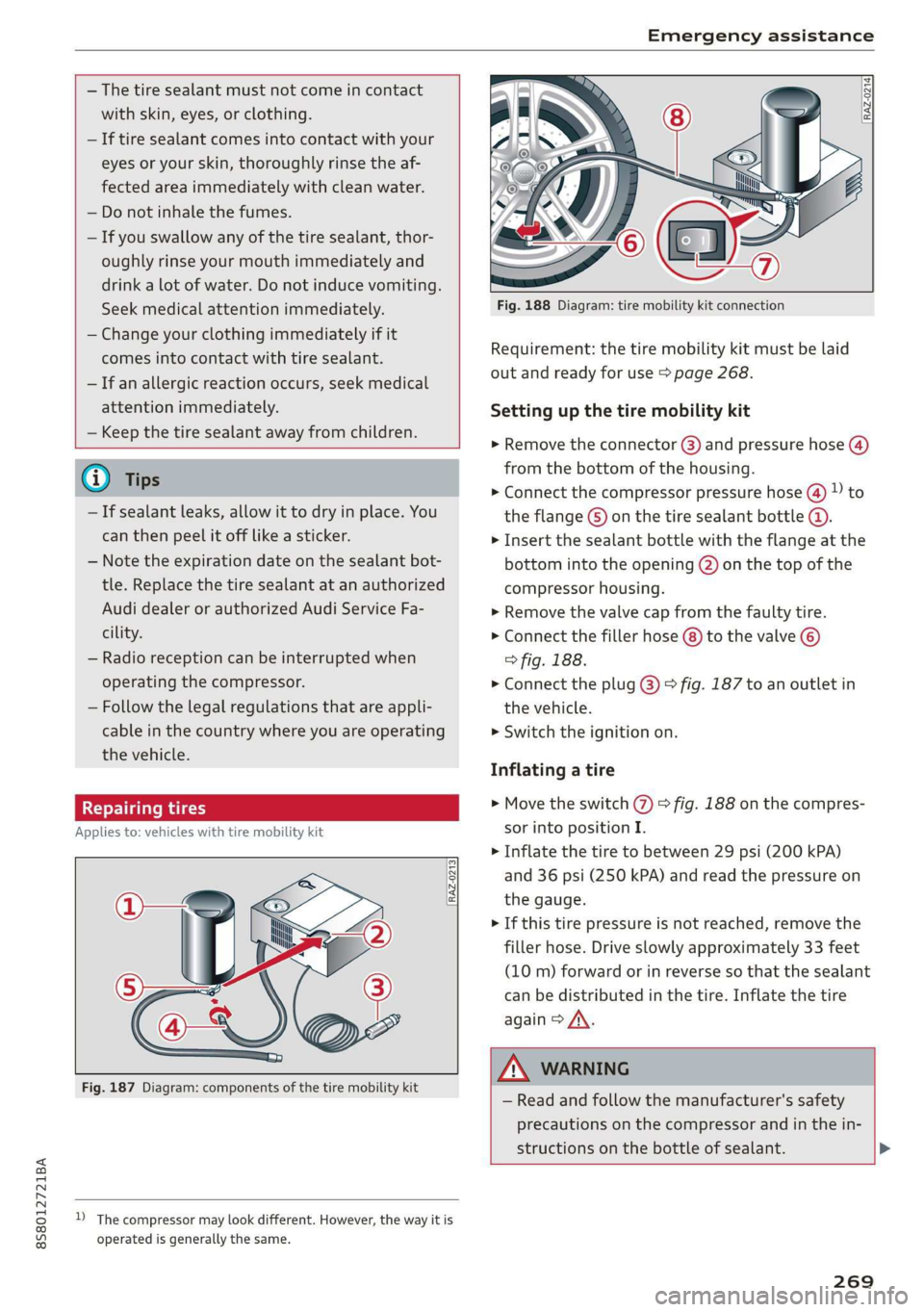
Fig. 187 Diagram: components of the tire mobility kit
D_ The compressor may look different. However, the way it is
operated is generally the same.
mo FP
aa Z, (Fy
Fig. 188 Diagram: tire mobility kit connection
Requirement: the tire mobility kit must be laid
out and ready for use > page 268.
Setting up the tire mobility kit
» Remove the connector @) and pressure hose (4)
from the bottom of the housing.
> Connect the compressor pressure hose (4) ) to
the flange ©) on the tire sealant bottle @.
> Insert the sealant bottle with the flange at the
bottom into the opening (2) on the top of the
compressor housing.
> Remove the valve cap from the faulty tire.
> Connect the filler hose (8) to the valve ©)
> fig. 188.
> Connect the plug @) > fig. 187 to an outlet in
the vehicle.
> Switch the ignition on.
Inflating a tire
> Move the switch (7) > fig. 188 on the compres-
sor into position I.
> Inflate the tire to between 29 psi (200 kPA)
and 36 psi (250 kPA) and read the pressure on
the gauge.
> If this tire pressure is not reached, remove the
filler hose. Drive slowly approximately 33 feet
(10 m) forward or in reverse so that the sealant
can be distributed in the tire. Inflate the tire
again > A\.
ZA WARNING
— Read and follow the manufacturer's safety
precautions on the compressor and in the in-
structions on the bottle of sealant. >
269
Page 277 of 304

8S8012721BA
Emergency assistance
If the vehicle should be towed with the axle
raised, then the ignition must be switched off to
reduce the risk of damage to the drivetrain.
Tow bar and towing cable
The vehicle can be towed with a tow bar or tow-
ing cable. Both drivers should be familiar with
the special considerations when towing, especial-
ly when using a towing cable.
Always make sure the traction force does not ex-
ceed the permitted level and there are no shock
loading conditions. There is always the risk of the
coupling becoming overloaded when driving off-
road.
For the most safety and security, drive with a tow
bar. You should use a towing cable only if a tow
bar is not available. Use a towing cable made of
synthetic elastic cable similar elastic material.
ZA\ WARNING
— Towing highly increases the risk of an acci-
dent, for example from colliding with the
towing vehicle.
— To reduce the risk of an accident, do not al-
low anyone to remain inside the vehicle
when it is being transported by a tow truck
or a special transporter.
@) Note
— If normal towing is not possible, for exam-
ple if the transmission is faulty or if the
towing distance is greater than 30 miles
(50 km), then transport the vehicle on a
special carrier.
— If the vehicle is towed by a tow truck at the
axle that is not permitted, this can cause se-
vere damage to the transmission.
— The vehicle must not be tow started for
technical reasons.
@) Tips
—If there is a power failure, the selector lever
will not move out of the "P" position. The
parking lock must be released using the
D_ Requirement: the vehicle battery must have a sufficient
charge level.
emergency release before towing the vehi-
cle > page 68.
— Follow the local legal regulations for tow-
ing.
Read and follow the important information under
=> page 274.
Preparations
> Only secure the towing cable or tow bar at the
designated towing loops > page 276,
=> page 276.
> Make sure the towing cable is not twisted. Oth-
erwise it could disconnect from the towing loop
while towing.
» Switch the emergency flashers on in both vehi-
cles > page 40. However, do not do this if it
prohibited by law.
Towing vehicle (front)
> Only start to drive when the towing cable is
taut.
> Be especially careful when accelerating.
> Avoid sudden braking or driving maneuvers.
Vehicle being towed (rear)
» Make sure the ignition is switched on so that
the steering wheel is not locked and so that you
can use the turn signals, the horn, and the
windshield wipers if needed > A\.
> The brake booster only works when the engine
is running. Power steering only works when the
ignition is switched on and the vehicle is roll-
ing )). If the brake booster and power steering
are not functioning, you must press the brake
pedal much harder and use more force to steer.
> Release the parking brake > page 59.
> Select the "N" selector lever position.
> Make sure the towing cable is always taut.
275
>
Page 279 of 304

8S58012721BA
Fuses and bulbs
Fuses and bulbs
Fuses
Replacing fuses
S 6
= o
q
= 2 % a.
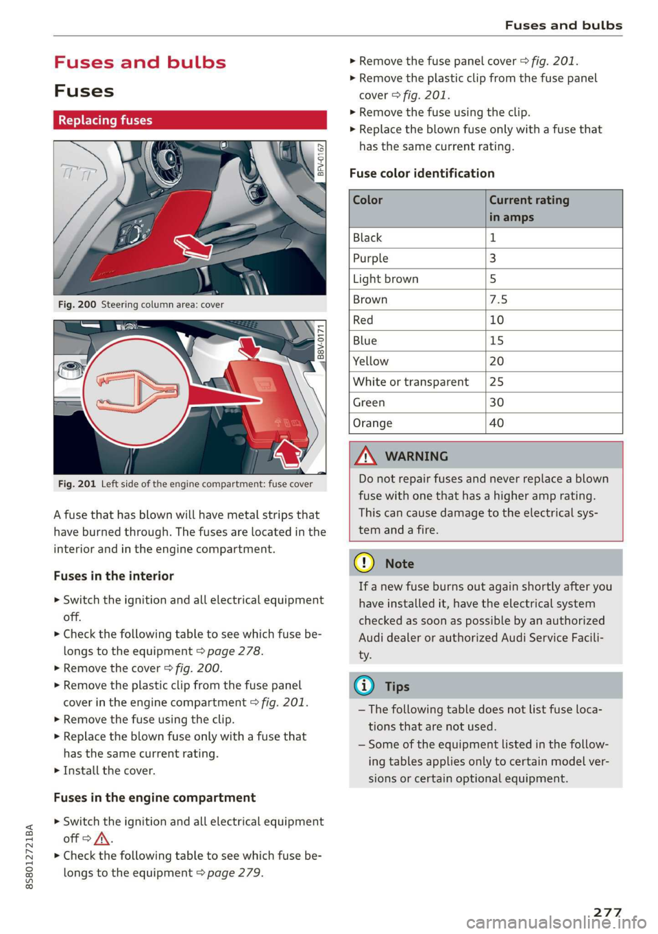
Fig. 201 Left side of the engine compartment: fuse cover
A fuse that has blown will have metal strips that
have burned through. The fuses are located in the
interior and in the engine compartment.
Fuses in the interior
> Switch the ignition and all electrical equipment
off.
> Check the following table to see which fuse be-
longs to the equipment > page 278.
» Remove the cover > fig. 200.
> Remove the plastic clip from the fuse panel
cover in the engine compartment © fig. 201.
> Remove the fuse using the clip.
> Replace the blown fuse only with a fuse that
has the same current rating.
> Install the cover.
Fuses in the engine compartment
> Switch the ignition and all electrical equipment
off > A\.
> Check the following table to see which fuse be-
longs to the equipment > page 279.
> Remove the fuse panel cover > fig. 201.
> Remove the plastic clip from the fuse panel
cover > fig. 201.
> Remove the fuse using the clip.
> Replace the blown fuse only with a fuse that
has the same current rating.
Fuse color identification
Color Current rating
in amps
Black 1
Purple 3
Light brown 5
Brown 1d
Red 10
Blue 15
Yellow 20
White or transparent [25
Green 30
Orange 40
Z\ WARNING
Do not repair fuses and never replace a blown
fuse with one that has a higher amp rating.
This can cause damage to the electrical sys-
tem and a fire.
CG) Note
If a new fuse burns out again shortly after you
have installed it, have the electrical system
checked as soon as possible by an authorized
Audi dealer or authorized Audi Service Facili-
ty.
@) Tips
— The following table does not list fuse loca-
tions that are not used.
— Some of the equipment listed in the follow-
ing tables applies only to certain model ver-
sions or certain optional equipment.
277
Page 281 of 304

8S58012721BA
Fuses and bulbs
Left engine compartment fuse assignment
B8V-0173
ment
Fig. 203 Left side of engine compartment: fuse assign-
No. Equipment
Fl ESC control module
F2 ESC control module
F3 Engine control module
F4
Engine components, engine cooling, sec-
ondary air pump
FS Engine components, tank system
Fo Brake light switch
F7 Engine components
F8 Heat oxygen sensor
F9 Engine components, exhaust door
F10 Fuel injectors, fuel control module
F13 Transmission fluid pump
F1l4 Ignition coils (5-cylinder)
Fis Horn
F16 Ignition coils
F17 Suppressor
F18
Diagnostic interface, battery monitoring,
garage door opener antenna
F19 Windshield wipers
F20
Anti-theft alarm system
No. Equipment
F21 Automatic transmission control module
F22
Terminal 50 diagnosis (engine control
module)
F23 Engine start
F31
Engine components (5-cylinder)
Bulbs
Cs
Your vehicle is equipped with maintenance-free
headlights and tail lights. However, if a light bulb
needs to be replaced, please contact an author-
ized Audi dealer or authorized Audi Service Facili-
ty.
279
Page 294 of 304

Index
Fueltank:capacity’. « csccex 2 mewn ee cme 285
Opening the fuel filler door............ 224
With reserve canister (emergency fueling) . 226
Fuses
ASSIQNIMENE. & cori: so comme 9 w soem © a sere 9 278
Replacing. ....... cece eee eee eee eee 277
G
GALA
refer to Speed dependent volume control. 175
Garage door opener... ...... cee eee ee eee 30
Gasoline... 2... eee eee 223
Additives... 2.0.0.2... 00. c cece eee 224
Gasoline: mixture wees s eiceas s wees os Howe 223
GAWR
refer to Gross Axle Weight Rating (GAWR) . 286
Global commands (voice recognition sys-
teM) 2. eee 105
Glossary of tire and loading terminology... 242
Glove compartment............ ee eee eee 49
G meter
refer to Sport displays.................. 15
Gross Axle Weight Rating (GAWR)........ 286
Gross Vehicle Weight Rating (GVWR)...... 286
GVWR
refer to Gross Vehicle Weight
Rating (GVWR) « scene < = eases 4 e Hams a eee 286
H
Handsfree... 1... eee eee eee
Headlight range control system
Headlight range control system (indicator
WGN) s sean ¢ s sews xs Hem ao Soe 2 2 Bae 2 a 20
Headlights .......... 00. cece 39
Cleaning’s < « ese =» gews ts ees e Sawn a ewe 263
Headlight range control system.......... 38
Washer system.......... 0.00 eee eee eee 42
Heated
EXteriGrMitrors: scm s : cum = + nome & : neues 41
Rear Wind OW 2s wes 5 wes 2 wenn ee omen 54
Seats... eee 54
Washer nozzles ......:ccseesecteeeeeee 42
Hex socket... 2.20... e eee eee eee 268
Hill descent control.................000. 65
Hill hold assist... 2.2.0.0... eee eee eee 61
also refer to Hill hold assist............. 61
292
Home address.............0000005 134, 138
HomeLink
refer to Garage door opener............. 30
FORM ac & csonene 2 6 sramne © wares oo cyaseas we © sirewere © 0 ae 6
THOESPOL 5 cxcwens w eeawens av rasenwe i & eeeoes © v anmueE 130
How many airbags does my vehicle have?.. 196
How safety belt pretensioners work....... 187
I
Ignition (indicator light)................- 18
Imbalance (wheels) ............000 eee ee 248
Immobilizer
refer to Electronic immobilizer........... 22
Important things to do before driving..... 177
Importing and exporting (contacts)....... 122
Improperly worn safety belts............ 187
Indicator lights............0.00020 22 eeee 7
‘Airbag SYSteM sau 2s eas so eee ae ween 200
PASSENGER AIR BAG ccc a x ces a x ewes » 200
INTANESEAatS s « cxcnscs ss asa oo come o wacioon oo 215
Input
Using the MME tOuUCR cies « « sos « 2 eon 3 os 94
Using the speller.......... 0.000.000 ee 98
Input level (media)................200- 163
Inspection interval..............0e eee ee 239
Installing child safety seats
Safety belts..................000000- 219
Instrument cluster.................0005- 10
M@SSAQES « sees is eee8 bv ose ey Pe es Hee 16
Operating’ « = esses 2 mason «2 en 6 eae a Os 12
Service interval display................ 239
Switching
tabs»... e008. cees sewn e cee 12
Instruments
Adjusting the lighting.................. 41
Interior lighting’: < 2 exe « = sees © s ness ¢ x seem 40
Intermittent (windshield wipers).......... 42
Internet
refer to CONhect. <2 zes5 ss wows = v Sewn a ee 125
Intertiet radio + seme: x s ween: 2 oem es eee ge 157
iPod
refer to Audi music interface....... 158,159
ITUNES tagGiNg « «ces ss peas ss pews vo ews 147
J
Joystick function (MMI) « » sms zs meen 2 yee 97
Page 299 of 304

8S58012721BA
Index
Seating position
Driver... ee ee eee 178
Front Passenger ies « » wives 3 ¥ asws oo ey & 179
How to adjust the front seats........... 179
Incorrect seat position................ 179
OGCUBANUS vem: « s wee 5 5 weER Fy Bee Ee 178
Seats
AGJUStING a: « 9 soos x 3 wees a ¢ caus 2 2 oem <9 46
Correct seating position............... 178
Number of seats................00008 182
Secondary phone..............200. 112,173
Selecting a source (media).............. 160
Selection menu..............0005 93,97,98
Selective door unlocking................. 21,
Selective wheel torque control............ 86
Selector lever (automatic transmission)
Emergency operation.................. 68
Position... 2.2... 0.5... c cece eee eee eee 62
Service and disposal
Safety belt pretensioner............... 188
Service interval display................. 239
Settings
Dir@GtOLy aces < = sees « 3 tees x 5 see ee eee 123
Ma Piss so soesia ow airenice © waivers «2 oenane wo ene 142
Media...... 0... eee eee eee eee eee 163
Navigation): « s sews s < exw x & eees 3 x ewe 138
RadiGise x crouse a i cwswaus 2 v comune a cuexene w 8 ao 150
SYStEM occ eee eee eee eee 171
Shift paddles (automatic transmission) .... . 66
Shuffle... 2... eee eee ee 163
Side airbags
Description...............0..02.0002 206
How theywork:: » s wea s 9 sees & o Hoes ¥ bow 208
Sidé assists zs swe : naam ¢ 2 mewem es em eo Be 75
Adjusting the brightness................ 77
Cleaning the sensors..............0--- 263
SeMSOPr Fane wesc s casa ss Hawes s ¥ Heres 5 ewe 75
Switching on and off................... 76
SIM Card r@ade@Pins «x ways : sane gs were « x ee 126
Ski DdGisw « x aeew « o meee « o eee s BeER os pe 50
Snowboatd, bag « ccs ss eeas xe eeea co RekS ee 50
Snow chains... .... 00. e eee eee eee ees 255
Socket
refer to Power sourceS.........-+--00+-- 48
Software update
refer to System update (MMI).......... 174
Software (MMI)
LIGGHSES « ssc & ¢ See & ¥ Rae & % HETES 3 £ er 176
Updates = sve es meme sean es wee ae ee 174
VERSION, «+ ewosase « « mmiomon © « wresnie w 6 poncene ev wx 174
Sources of information about child restraints
and theiruse............... eee eee ee 222
Spare tire... .... eee eee eee 274
Speed dependent volume control......... 175
Speedometer. consis x + emcee x « susie s v aves 9 6 a 10
Speed warning systeMisescs ows oo ssiae ao one 70
Speller's s « sess x x sews « ¥ saves vo Heres e Rees 98
SPOFUGISPIBYS « sus « x seme 2 2 wee sy eee we 15
SpOrtode-: « s sees ¢ » wees cs wees so wees 87
Sport view...........0 0.00. 13
Stabilization program
refer to Electronic Stabilization
Comtroli(ESO):. x sscoons w 0 avescos ow awcvane w seawness 86
START Engine STOP button............... 57
START ENGINE STOP (button)............. 58
Starting to-drive:s «ease ss news xs Hes ss Bene 61
Starting (CNgine) «=< soe st owes sy ee se ws 57
Steering... 6. cece eee 89
Indicator light « sacs ¢ ¢ ames ¥ gee se cos 18
also refer to Steering..............0005 89
Steering wheel
AdjUStINg . 0. eee eee eee 57
Shift paddles (automatic transmission) .... 66
also refer to Multifunction
steering wheel..............-..000-- 12,14
Steps for determining correct load limit... 253
Stopover (navigation) ................4 137
Storage compartments............0.0005 49
Streaming
refer to Online media................. 157
S tronic (automatic transmission) .......... 61
Subtitles (DVD) « assswe 3 « wasn ov soe ¥ « ees 163
SUTVISONS 2 same 2 2 qason = ¥ eee + eee us we @ 42
SUSPENSION CONOliss ¢ s new s ¥ wares s & wows ¥ 78
Swapping calls; < sews ss agus ss sees 5 tees 116
Switching daytime running lights on and off. 40
Switching the ignitionon................. 57
297