Page 33 of 100
Instrument and control functions
3-19
3
Ri
der seat
To remove the rider seat
1. Remove the passenger seat.
2. Remove the center cover by re- moving the screws.
3. Remove the rider seat by remov- ing the bolts. Lift the rear of the
rider seat and pull it backward.
To install the rider seat
1. Insert the projection on the front of the rider seat into the seat holder
as shown, and then place the seat
in the original position. 2. Install the rider seat bolts.
3. Install the center cover by install-
ing the screws.
4. Install the passenger seat.
TIP
Make sure that the seats are properly
secured before riding.
1. Center cover
2. Screw
1. Rider seat
2. Bolt
1 2
12
1. Projection
2. Seat holder
1
2
UBR5E0E0.book Page 19 Wednesday, July 5, 2017 11:10 AM
Page 34 of 100
Instrument and control functions
3-20
3
EAU62930
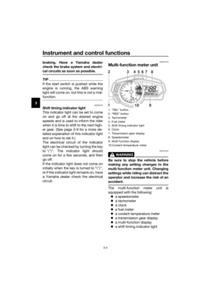
Helmet hold ers
The helmet holders are located on the
bottom of the passenger seat.
To secure a helmet to a helmet hol d-
er 1. Remove the passenger seat. (See page 3-18.)
2. Attach a helmet to a helmet hold- er, and then securely install the
passenger seat. WARNING! Nev-
er ri de with a helmet attached to
the helmet hol der, since the hel-
met may hit o bjects, causin g
loss of control and possibly an
acci dent.
[EWA10162]
To release a helmet from a helmet
hol der
Remove the passenger seat, remove
the helmet from the helmet holder, and
then install the seat.
1. Helmet holder
1. Helmet
2. Passenger seat
1
1
2
UBR5E0E0.book Page 20 Wednesday, July 5, 2017 11:10 AM
Page 35 of 100
Instrument and control functions
3-21
3
EAU62550
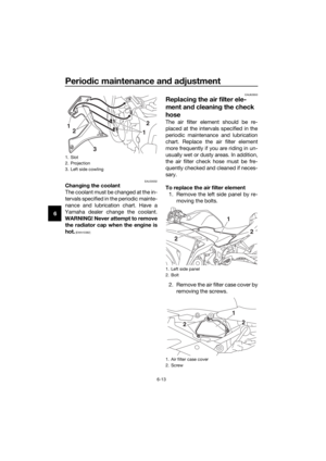
Stora ge compartment
The storage compartment is located
under the passenger seat. (See page
3-18.)
When storing documents or other
items in the storage compartment, be
sure to wrap them in a plastic bag so
that they will not get wet. When wash-
ing the vehicle, be careful not to let any
water enter the storage compartment.
WARNING
EWA15401
Do not exceed the maximum loa d of
160 k g (353 l b) for the vehicle.
EAU39672
Rear view mirrors
The rear view mirrors of this vehicle
can be folded forward or backward for
parking in narrow spaces. Fold the mir-
rors back to their original position be-
fore riding.
WARNING
EWA14372
Be sure to fol d the rear view mirrors
b ack to their ori ginal position before
ri din g.
1. Storage compartment
1
1. Riding position
2. Parking position
11
22
22
UBR5E0E0.book Page 21 Wednesday, July 5, 2017 11:10 AM
Page 36 of 100

Instrument and control functions
3-22
3
EAU68141
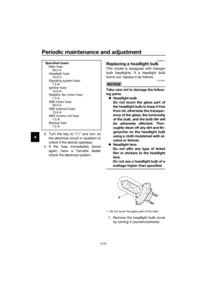
A djustin g the shock a bsorb er
assem bly
This shock absorber assembly is
equipped with a spring preload adjust-
ing ring.
NOTICE
ECA10102
To avoi d d amag ing the mechanism,
d o not attempt to turn b eyond the
maximum or minimum settin gs.
Adjust the spring preload as follows.
1. Remove the drive chain guard by removing the bolts and collars.
2. To increase the spring preload and thereby harden the suspen-
sion, turn the adjusting ring in di-
rection (a). To decrease the spring
preload and thereby soften the
suspension, turn the adjusting ring
in direction (b). Align the appropriate notch in
the adjusting ring with the po-
sition indicator on the shock
absorber.
Use the special wrench and
the extension bar included in
the owner’s tool kit to make
the adjustment. 3. Install the drive chain guard by in-
stalling the collars and bolts, and
then tighten the bolts to the spec-
ified torque.
1. Drive chain guard
2. Bolt and collar
2
1
1. Extension bar
2. Special wrench
3. Spring preload adjusting ring
4. Position indicator
Sprin g preloa d settin g:
Minimum (soft): 1
Standard: 3
Maximum (hard):
7
Ti ghtening torque:
Drive chain guard bolt: 10 N·m (1.0 kgf·m, 7.4 lb·ft)
7654321
4
(b)
(a)
32
1
UBR5E0E0.book Page 22 Wednesday, July 5, 2017 11:10 AM
Page 37 of 100

Instrument and control functions
3-23
3
EAU15152
Lugg ag e strap hol ders
There is a luggage strap holder on
each passenger footrest.
EAU15306
Si destan d
The sidestand is located on the left
side of the frame. Raise the sidestand
or lower it with your foot while holding
the vehicle upright.
TIP
The built-in sidestand switch is part of
the ignition circuit cut-off system,
which cuts the ignition in certain situa-
tions. (See the following section for an
explanation of the ignition circuit cut-
off system.)
WARNING
EWA10242
The vehicle must not be ri dden with
the si destan d d own, or if the si de-
stan d cannot b e properly move d up
(or does not stay up), otherwise the
si destan d coul d contact the groun d
an d d istract the operator, resultin g
in a possi ble loss of control.
Yamaha’s i gnition circuit cut-off
system has been desi gne d to assist
the operator in fulfillin g the respon-
si bility of raisin g the si destan d b e-
fore startin g off. Therefore, check
this system re gularly an d have a
Yamaha dealer repair it if it does not
function properly.
1. Luggage strap holder
1
UBR5E0E0.book Page 23 Wednesday, July 5, 2017 11:10 AM
Page 38 of 100
Instrument and control functions
3-24
3
EAU66730
Ig nition circuit cut-off system
The ignition circuit cut-off system
(comprising the sidestand switch,
clutch switch and neutral switch) has
the following functions.
It prevents starting when the
transmission is in gear and the
sidestand is up, but the clutch le-
ver is not pulled.
It prevents starting when the
transmission is in gear and the
clutch lever is pulled, but the side-
stand is still down.
It cuts the running engine when
the transmission is in gear and the
sidestand is moved down.
Periodically check the operation of the
ignition circuit cut-off system accord-
ing to the following procedure.
UBR5E0E0.book Page 24 Wednesday, July 5, 2017 11:10 AM
Page 39 of 100

Instrument and control functions
3-25
3
With the engine turned off:
1. Move the sidestand down.
2.
Make sure that the engine stop switch
is set to “ ”.
3. Turn the key on.
4. Shift the transmission into the neutral position.
5. Push the start switch.
Does the engine start?
With the engine still running:
6. Move the sidestand up.
7. Keep the clutch lever pulled.
8. Shift the transmission into gear.
9. Move the sidestand down.
Does the engine stall?
After the engine has stalled:
10. Move the sidestand up.
11. Keep the clutch lever pulled.
12. Push the start switch.
Does the engine start?
The system is OK. The motorcycle can
be ridden.
The neutral switch may not be working
correctly.
The motorcycle should not be ridden
until checked by a Yamaha dealer.
The sidestand switch may not be
working correctly.
The motorcycle should not be ridden
until checked by a Yamaha dealer.
The clutch switch may not be working
correctly.
The motorcycle should not be ridden
until checked by a Yamaha dealer.
WARNING
If a malfunction is noted, have a
Yamaha dealer check the system
before riding.
YES NO
YESNO
YESNO
UBR5E0E0.book Page 25 Wednesday, July 5, 2017 11:10 AM
Page 40 of 100

For your safety – pre-operation checks
4-1
4
EAU63440
Inspect your vehicle each time you use it to make sure the vehicle is in safe oper-
ating condition. Always follow the inspection and maintenance procedures and
schedules described in the Owner’s Manual.
WARNING
EWA11152
Failure to inspect or maintain the vehicle properly increases the possibility
of an acci dent or equipment d amage. Do not operate the vehicle if you fin d
any pro blem. If a pro blem cannot be correcte d b y the proce dures provi ded
in this manual, have the vehicle inspecte d b y a Yamaha dealer.
Before using this vehicle, check the following points:
ITEM CHECKSPAGE
Fuel • Check fuel level in fuel tank.
• Refuel if necessary.
• Check fuel line for leakage.
• Check fuel tank breather hose and overflow hose for
obstructions, cracks or damage, and check hose con-
nections. 3-16,
3-17
En gine oil • Check oil level in engine.
• If necessary, add recommended oil to specified level.
• Check vehicle for oil leakage. 6-8
Coolant • Check coolant level in reservoir.
• If necessary, add recommended coolant to specified
level.
• Check cooling system for leakage. 6-11
Front brake • Check operation.
• If soft or spongy, have Yamaha dealer bleed hydraulic
system.
• Check brake pads for wear.
• Replace if necessary.
• Check fluid level in reservoir.
• If necessary, add specified brake fluid to specified level.
• Check hydraulic system for leakage. 6-21,
6-22
Rear brake • Check operation.
• If soft or spongy, have Yamaha dealer bleed hydraulic
system.
• Check brake pads for wear.
• Replace if necessary.
• Check fluid level in reservoir.
• If necessary, add specified brake fluid to specified level.
• Check hydraulic system for leakage. 6-21,
6-22
Clutch • Check operation.
• Lubricate cable if necessary.
• Check lever free play.
• Adjust if necessary. 6-18
UBR5E0E0.book Page 1 Wednesday, July 5, 2017 11:10 AM


When storing documents or other
items in the storage")
 has
the follow")