Page 57 of 100

Periodic maintenance an d a djustment
6-12
6
3. If the coolant is at or below the mi-
nimum level mark, remove the left
side cowling and coolant reservoir
cover to access the coolant reser-
voir.
4. Remove the coolant reservoir cap, add coolant to the maximum level
mark, and then install the reservoir
cap. WARNING! Remove only
the coolant reservoir cap. Never
attempt to remove the ra diator
cap when the en gine is hot.
[EWA15162] NOTICE: If coolant is not
availa ble, use distille d water or
soft tap water instea d. Do not
use har d water or salt water
since it is harmful to the en gine.
If water has been used instead
of coolant, replace it with cool- ant as soon as possi
ble, other-
wise the coolin g system will not
b e protecte d a gainst frost an d
corrosion. If water has been
a dd ed to the coolant, have a
Yamaha dealer check the anti-
freeze content of the coolant as
soon as possi ble, otherwise the
effectiveness of the coolant will
b e red uced.
[ECA10473]
5. Install the coolant reservoir cover.
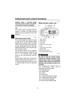
6. Install the left side cowling by in-
stalling the bolts.
TIP
Fit the projections on the cowling into
the slots as shown.
1. Left side cowling
2. Bolt
1. Bolt
2. Coolant reservoir cover
2
1
22
2
1
1. Coolant reservoir cap
Coolant reservoir capacity (up to
the maximum level mark):
0.25 L (0.26 US qt, 0.22 Imp.qt)
1
UBR5E0E0.book Page 12 Wednesday, July 5, 2017 11:10 AM
Page 58 of 100

Periodic maintenance an d a djustment
6-13
6
EAU33032Chan gin g the coolant
The coolant must be changed at the in-
tervals specified in the periodic mainte-
nance and lubrication chart. Have a
Yamaha dealer change the coolant.
WARNING! Never attempt to remove the ra diator cap when the en gine is
hot.
[EWA10382] EAU62650
Replacin
g the air filter ele-
ment an d cleanin g the check
hose
The air filter element should be re-
placed at the intervals specified in the
periodic maintenance and lubrication
chart. Replace the air filter element
more frequently if you are riding in un-
usually wet or dusty areas. In addition,
the air filter check hose must be fre-
quently checked and cleaned if neces-
sary.
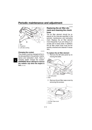
To replace the air filter element
1. Remove the left side panel by re- moving the bolts.
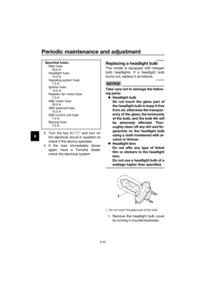
2. Remove the air filter case cover by removing the screws.
1. Slot
2. Projection
3. Left side cowling
3
12
2
1
1. Left side panel
2. Bolt
1. Air filter case cover
2. Screw
2
2
1
1
2
2
UBR5E0E0.book Page 13 Wednesday, July 5, 2017 11:10 AM
Page 59 of 100
Periodic maintenance an d a djustment
6-14
6
3. Pull the air filter element out.
4. Insert a new air filter element into
the air filter case. NOTICE: Make
sure that the air filter element is
properly seated in the air filter
case. The en gine shoul d never
b e operated without the air filter
element installed , otherwise the
piston(s) an d/or cylin der(s) may
b ecome excessively worn.
[ECA10482]
5. Install the air filter case cover by
installing the screws.
6. Install the left side panel by install- ing the bolts.
To clean the air filter check hose 1. Check the hose on the front of the air filter case for accumulated dirt
or water. 2. If dirt or water is visible, remove
the hose, clean it, and then install
it.
1. Air filter element
1. Air filter check hose
1
1
UBR5E0E0.book Page 14 Wednesday, July 5, 2017 11:10 AM
Page 60 of 100
Periodic maintenance an d a djustment
6-15
6
EAU21386
Checkin g the throttle grip free
play
Measure the throttle grip free play as
shown.
Periodically check the throttle grip free
play and, if necessary, have a Yamaha
dealer adjust it.
EAU21402
Valve clearance
The valve clearance changes with use,
resulting in improper air-fuel mixture
and/or engine noise. To prevent this
from occurring, the valve clearance
must be adjusted by a Yamaha dealer
at the intervals specified in the periodic
maintenance and lubrication chart.
1. Throttle grip free play
Throttle grip free play:
3.0–5.0 mm (0.12–0.20 in)
1
UBR5E0E0.book Page 15 Wednesday, July 5, 2017 11:10 AM
Page 61 of 100

Periodic maintenance an d a djustment
6-16
6
EAU69760
Tires
Tires are the only contact between the
vehicle and the road. Safety in all con-
ditions of riding depends on a relatively
small area of road contact. Therefore, it
is essential to maintain the tires in good
condition at all times and replace them
at the appropriate time with the speci-
fied tires.
Tire air pressure
The tire air pressure should be
checked and, if necessary, adjusted
before each ride.
WARNING
EWA10504
Operation of this vehicle with im-
proper tire pressure may cause se-
vere injury or d eath from loss of
control. The tire air pressure must be
checked and a djuste d on col d
tires (i.e., when the temperature
of the tires equals the am bient
temperature).
The tire air pressure must be
a d juste d in accor dance with the
ri din g speed and with the total
wei ght of ri der, passen ger, car-
g o, an d accessories approve d
for this mo del.
WARNING
EWA10512
Never overloa d your vehicle. Opera-
tion of an overloa ded vehicle coul d
cause an acci dent.
Tire inspection
The tires must be checked before each
ride. If the center tread depth reaches
the specified limit, if the tire has a nail
or glass fragments in it, or if the side-
wall is cracked, have a Yamaha dealer
replace the tire immediately.
Tire air pressure (measure d on col d
tires): 1 person: Front:
200 kPa (2.00 kgf/cm2, 29 psi)
Rear: 250 kPa (2.50 kgf/cm2, 36 psi)
2 persons: Front:200 kPa (2.00 kgf/cm2, 29 psi)
Rear: 250 kPa (2.50 kgf/cm2, 36 psi)
Maximum loa d*:
160 kg (353 lb)
* Total weight of rider, passenger, cargo and accessories
1. Tire sidewall
2. Tire tread depth
UBR5E0E0.book Page 16 Wednesday, July 5, 2017 11:10 AM
Page 62 of 100

Periodic maintenance an d a djustment
6-17
6
TIP
The tire tread depth limits may differ
from country to country. Always com-
ply with the local regulations.
WARNING
EWA10472
Have a Yamaha dealer replace
excessively worn tires. Besi des
b ein g ille gal, operatin g the vehi-
cle with excessively worn tires
d ecreases ri din g sta bility an d
can lead to loss of control.
The replacement of all wheel
and b rake-relate d parts, inclu d-
in g the tires, shoul d b e left to a
Yamaha dealer, who has the
necessary professional knowl-
e dge an d experience to do so.
Ride at mo derate spee ds after
chan gin g a tire since the tire
surface must first be “ broken
in” for it to develop its optimal
characteristics.
Tire information
This model is equipped with tubeless
tires and rubber tire air valves.
Tires age, even if they have not been
used or have only been used occasion-
ally. Cracking of the tread and sidewall
rubber, sometimes accompanied by
carcass deformation, is an evidence of
ageing. Old and aged tires shall be
checked by tire specialists to ascertain
their suitability for further use.
WARNING
EWA10462
The front an d rear tires shoul d b e of
the same make an d d esi gn, other-
wise the han dlin g characteristics of
the vehicle may be different, which
coul d lea d to an acci dent.
After extensive tests, only the tires list-
ed below have been approved for this
model by Yamaha.
Minimum tire trea d d epth (front an d
rear): 1.6 mm (0.06 in)
Front tire:Size:
110/70-17M/C (54H)
Manufacturer/model: MICHELIN/PILOT STREET
Rear tire: Size:140/70-17M/C (66H)
Manufacturer/model: MICHELIN/PILOT STREET
UBR5E0E0.book Page 17 Wednesday, July 5, 2017 11:10 AM
Page 63 of 100

Periodic maintenance an d a djustment
6-18
6
EAU21963
Cast wheels
To maximize the performance, durabil-
ity, and safe operation of your vehicle,
note the following points regarding the
specified wheels.
The wheel rims should be
checked for cracks, bends, warp-
age or other damage before each
ride. If any damage is found, have
a Yamaha dealer replace the
wheel. Do not attempt even the
smallest repair to the wheel. A de-
formed or cracked wheel must be
replaced.
The wheel should be balanced
whenever either the tire or wheel
has been changed or replaced. An
unbalanced wheel can result in
poor performance, adverse han-
dling characteristics, and a short-
ened tire life.
EAU62663
Adjustin g the clutch lever free
play
Measure the clutch lever free play as
shown.
Periodically check the clutch lever free
play and, if necessary, adjust it as fol-
lows.
1. Loosen the locknut at the clutch lever.
2. To increase the clutch lever free play, turn the clutch lever free play
adjusting bolt in direction (a). To
decrease the clutch lever free
play, turn the adjusting bolt in di-
rection (b).
TIP
If the specified clutch lever free play
could be obtained as described above,
skip steps 3–8.
3. Fully turn the adjusting bolt at theclutch lever in direction (a) to loos-
en the clutch cable.
4. Remove the right side cowling by removing the bolts.
1. Clutch lever free play adjusting bolt
2. Locknut
3. Clutch lever free play
Clutch lever free play:10.0–15.0 mm (0.39–0.59 in)
321
(a)
(b)
UBR5E0E0.book Page 18 Wednesday, July 5, 2017 11:10 AM
Page 64 of 100
Periodic maintenance an d a djustment
6-19
6 5. Loosen the locknut at the crank-
case.
6. To increase the clutch lever free play, turn the clutch lever free play
adjusting nut in direction (a). To
decrease the clutch lever free
play, turn the adjusting nut in di-
rection (b).
7. Tighten the locknut at the crank- case.
8. Install the right side cowling by in- stalling the bolts.
TIP
Fit the projections on the cowling into
the slots as shown.
9. Tighten the locknut at the clutchlever.
1. Right side cowling
2. Bolt
1. Locknut
2. Clutch lever free play adjusting nut
2
1
2
2
2
(b)
(a)
1
1. Slot
2. Projection
3. Right side cowling
3
1
22
1
UBR5E0E0.book Page 19 Wednesday, July 5, 2017 11:10 AM


. To
dec")