Page 33 of 98

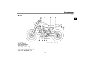
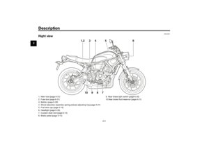
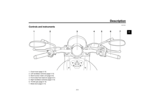
Instrument and control functions
3-18
3
EAU55512
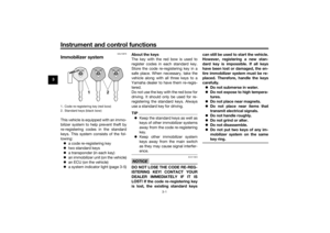
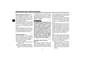
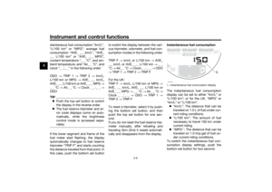
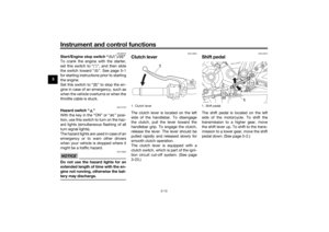
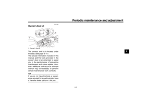
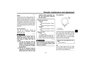
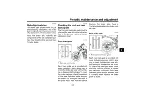
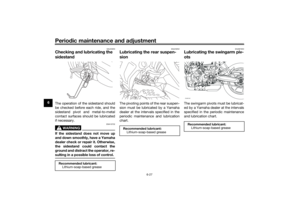
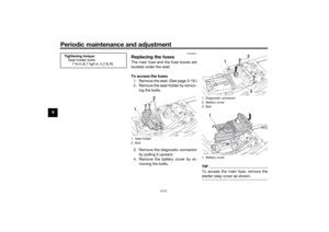
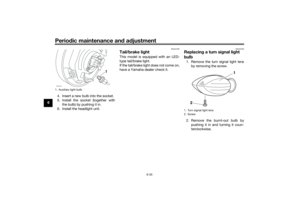
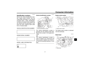
Fuel tank breather hose and
overflow hoseBefore operating the motorcycle:
Check each hose connection.
Check each hose for cracks or
damage, and replace if necessary.
Make sure that the end of each
hose is not blocked, and clean if
necessary.
Make sure that each hose is rout-
ed through the clamp.
Make sure that the paint mark on
each hose is below the clamp.
EAU13434
Catalytic converterThis model is equipped with a catalytic
converter in the exhaust system.
WARNING
EWA10863
The exhaust system is hot after op-
eration. To prevent a fire hazard or
burns:
Do not park the vehicle near
possible fire hazards such as
grass or other materials that
easily burn.
Park the vehicle in a place
where pedestrians or children
are not likely to touch the hot
exhaust system.
Make sure that the exhaust sys-
tem has cooled down before
doing any maintenance work.
Do not allow the engine to idle
more than a few minutes. Long
idling can cause a build-up of
heat.
NOTICE
ECA10702
Use only unleaded gasoline. The use
of leaded gasoline will cause unre-
pairable damage to the catalytic
converter.
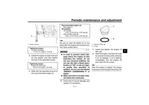
1. Fuel tank overflow hose
2. Fuel tank breather hose
3. Original position (paint mark)
4. Clamp
4
31
2
UBU3E1E0.book Page 18 Monday, June 4, 2018 5:20 PM
Page 34 of 98

Instrument and control functions
3-19
3
EAU83140
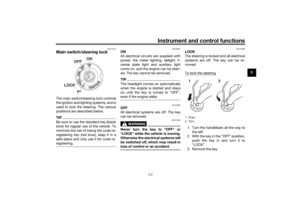
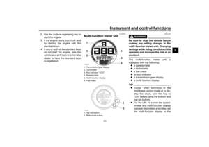
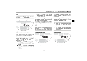
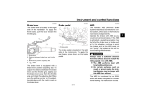
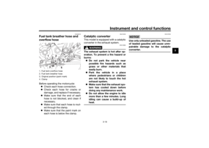
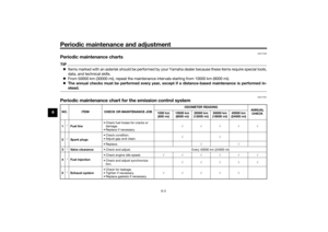
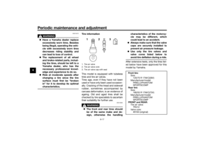
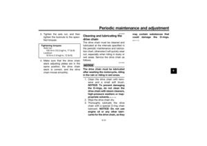
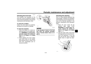
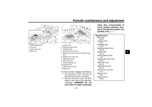
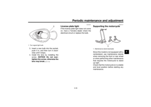
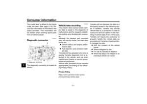
SeatTo remove the seat
Insert the key into the seat lock, turn it
counterclockwise, and then pull the
seat off.
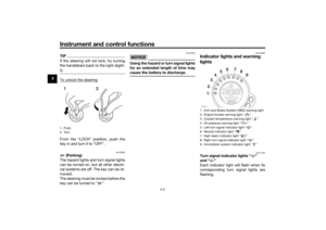
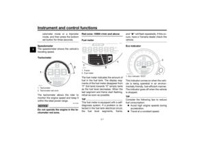
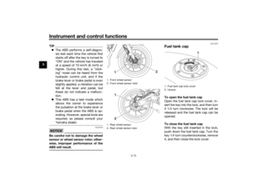
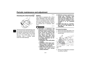
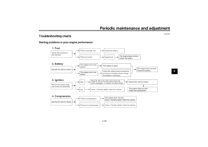
To install the seat
Fit the slot in the seat onto the projec-
tion as shown, orient the seat in order
to insert the seat bracket into the seat
lock, push the rear of the seat down to
lock it in place, and then remove the
key.
TIPMake sure that the seat is properly se-
cured before riding.
EAUM3640
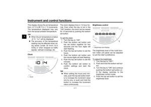
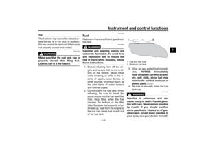
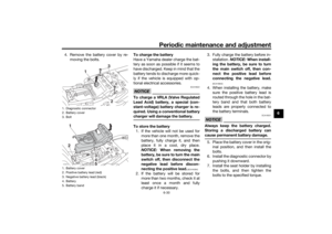
Helmet holding cableA helmet holding cable is located un-
der the seat. Use this cable in conjunc-
tion with the screwdriver to secure a
helmet to the vehicle.
To secure a helmet with the helmet
holding cable
1. Remove the seat. (See page 3-19.)
2. Remove the screwdriver from its
holders by pulling it up from the
left side, and then remove the hel-
met holding cable from the screw-
driver.
1. Seat lock
2. Unlock.ZAUM1344
2
1
1. Slot
2. Projection
3. Seat bracket
4. Seat lock
1
3
4
2
1. Helmet holding cable
2. ScrewdriverZAUM1359
12
UBU3E1E0.book Page 19 Monday, June 4, 2018 5:20 PM
Page 35 of 98

Instrument and control functions
3-20
3
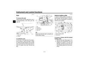
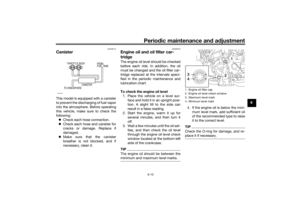
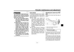
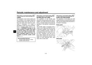
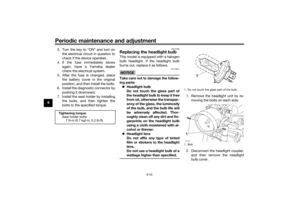
3. Pass the helmet holding cable
through the buckle on the helmet
strap.
4. Hook the cable loops over the
screwdriver, and then install the
screwdriver first into the right-side
holder and then into the left-side
holder.
TIPMake sure that the screwdriver is se-
curely positioned between its holders,
and then position the cable loops to
the right of the machine before install-
ing the seat.
5. Install the passenger seat.
WARNING! Never ride with a
helmet attached to the helmet
holder, since the helmet may hit
objects, causing loss of control
and possibly an accident.
[EWA10162]
To release a helmet from the helmet
holding cable
1. Remove the seat.
2. Remove the screwdriver, then re-
move the helmet holding cable
from the helmet.
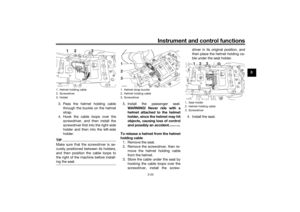
3. Store the cable under the seat by
hooking the cable loops over the
screwdriver, install the screw-driver in its original position, and
then place the helmet holding ca-
ble under the seat holder.
4. Install the seat.
1. Helmet holding cable
2. Screwdriver
3. HolderZAUM1360
1. Helmet strap buckle
2. Helmet holding cable
3. ScrewdriverZAUM1361123
1. Seat holder
2. Helmet holding cable
3. ScrewdriverZAUM1362
UBU3E1E0.book Page 20 Monday, June 4, 2018 5:20 PM
Page 36 of 98

Instrument and control functions
3-21
3
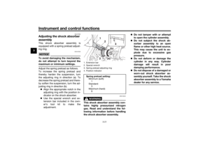
EAU47002
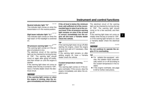
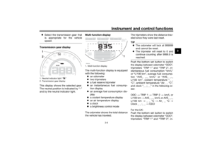
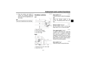
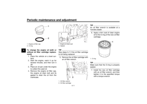
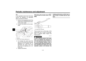
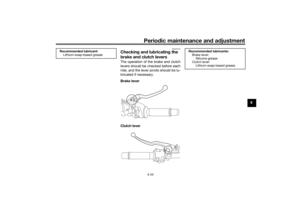
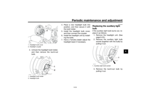
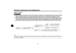
Adjusting the shock absorber
assemblyThis shock absorber assembly is
equipped with a spring preload adjust-
ing ring.NOTICE
ECA10102
To avoid damaging the mechanism,
do not attempt to turn beyond the
maximum or minimum settings.Adjust the spring preload as follows.
To increase the spring preload and
thereby harden the suspension, turn
the adjusting ring in direction (a). To
decrease the spring preload and there-
by soften the suspension, turn the ad-
justing ring in direction (b).
Align the appropriate notch in the
adjusting ring with the position in-
dicator on the shock absorber.
Use the special wrench and ex-
tension bar included in the own-
er’s tool kit to make the
adjustment.
WARNING
EWA10222
This shock absorber assembly con-
tains highly pressurized nitrogen
gas. Read and understand the fol-
lowing information before handling
the shock absorber assembly.Do not tamper with or attempt
to open the cylinder assembly.
Do not subject the shock ab-
sorber assembly to an open
flame or other high heat source.
This may cause the unit to ex-
plode due to excessive gas
pressure.
Do not deform or damage the
cylinder in any way. Cylinder
damage will result in poor
damping performance.
Do not dispose of a damaged or
worn-out shock ab
sorber as-
sembly yourself. Take the shock
absorber assembly to a Yamaha
dealer for any service.
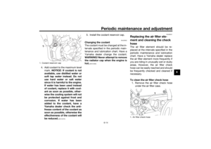
1. Extension bar
2. Special wrench
3. Spring preload adjusting ring
4. Position indicatorSpring preload setting:
Minimum (soft):
1
Standard:
3
Maximum (hard):
9
7 6
9 8 5 4 3 2 1
3(a)(b)
2
1
4
UBU3E1E0.book Page 21 Monday, June 4, 2018 5:20 PM
Page 37 of 98

Instrument and control functions
3-22
3
EAU70641
Auxiliary DC connectorThis vehicle is equipped with an auxil-
iary DC connector. Consult your
Yamaha dealer before installing any
accessories.
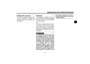
EAU15306
SidestandThe sidestand is located on the left
side of the frame. Raise the sidestand
or lower it with your foot while holding
the vehicle upright.TIPThe built-in sidestand switch is part of
the ignition circuit cut-off system,
which cuts the ignition in certain situa-
tions. (See the following section for an
explanation of the ignition circuit cut-
off system.)
WARNING
EWA10242
The vehicle must not be ridden with
the sidestand down, or if the side-
stand cannot be properly moved up
(or does not stay up), otherwise the
sidestand could contact the ground
and distract the operator, resulting
in a possible loss of control.
Yamaha’s ignition circuit cut-off
system has been designed to assist
the operator in fulfilling the respon-
sibility of raising the sidestand be-
fore starting off. Therefore, checkthis system regularly and have a
Yamaha dealer repair it if it does not
function properly.
UBU3E1E0.book Page 22 Monday, June 4, 2018 5:20 PM
Page 38 of 98
Instrument and control functions
3-23
3
EAU44895
Ignition circuit cut-off systemThis system prevents in-gear engine
starts unless the clutch lever is pulled
and the sidestand is up. Also, it will
stop the running engine should the
sidestand be lowered while the trans-
mission is in gear.
Periodically check the system via the
following procedure.TIPThis check is most reliable if per-
formed with a warmed-up engine.
See pages 3-2 and 3-12 for switch
operation information.
UBU3E1E0.book Page 23 Monday, June 4, 2018 5:20 PM
Page 39 of 98

Instrument and control functions
3-24
3
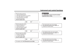
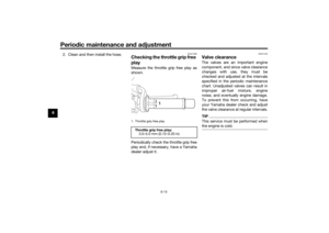
With the engine turned off:
1. Move the sidestand down.
2. Set engine stop switch to run position.
3. Turn main switch to on position.
4. Shift transmission into neutral.
5. Push the start switch.
Does the engine start?
With the engine still running:
6. Move the sidestand up.
7. Pull the clutch lever.
8. Shift transmission into gear.
9. Move the sidestand down.
Does the engine stall?
After the engine has stalled:
10. Move the sidestand up.
11. Pull the clutch lever.
12. Push the start switch.
Does the engine start?
The system is OK. The motorcycle can be ridden.
YES NO YES NO YES NO
The neutral switch may not be working.
The motorcycle should not be ridden until
checked by a Yamaha dealer.
The clutch switch may not be working.
The motorcycle should not be ridden until
checked by a Yamaha dealer.The sidestand switch may not be working.
The motorcycle should not be ridden until
checked by a Yamaha dealer.If a malfunction is found, have the vehicle
inspected before riding.
WARNING
UBU3E1E0.book Page 24 Monday, June 4, 2018 5:20 PM
Page 40 of 98

For your safety – pre-operation checks
4-1
4
EAU15599
Inspect your vehicle each time you use it to make sure the vehicle is in safe operating condition. Always follow the inspection
and maintenance procedures and schedules described in the Owner’s Manual.
WARNING
EWA11152
Failure to inspect or maintain the vehicle properly increases the possibility of an accident or equipment damage.
Do not operate the vehicle if you find any problem. If a problem cannot be corrected by the procedures provided in
this manual, have the vehicle inspected by a Yamaha dealer.Before using this vehicle, check the following points:
ITEM CHECKS PAGE
Fuel• Check fuel level in fuel tank.
• Refuel if necessary.
• Check fuel line for leakage.
• Check fuel tank breather hose and overflow hose for obstructions, cracks or
damage, and check hose connections.3-16, 3-18
Engine oil• Check oil level in engine.
• If necessary, add recommended oil to specified level.
• Check vehicle for oil leakage.6-10
Coolant• Check coolant level in reservoir.
• If necessary, add recommended coolant to specified level.
• Check cooling system for leakage.6-13
Front brake• Check operation.
• If soft or spongy, have Yamaha dealer bleed hydraulic system.
• Check brake pads for wear.
• Replace if necessary.
• Check fluid level in reservoir.
• If necessary, add specified brake fluid to specified level.
• Check hydraulic system for leakage.6-20, 6-21
UBU3E1E0.book Page 1 Monday, June 4, 2018 5:20 PM