Page 25 of 98
, ŌĆ£_ _._ŌĆØ is displayed.Average fuel consumption
This display shows the average fuel
consumption since it wa")
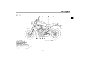
Instrument and control functions
3-10
3
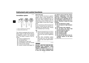
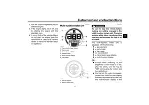
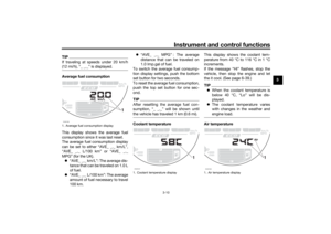
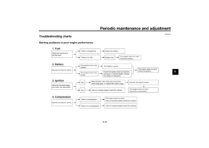
TIPIf traveling at speeds under 20 km/h
(12 mi/h), ŌĆ£_ _._ŌĆØ is displayed.Average fuel consumption
This display shows the average fuel
consumption since it was last reset.
The average fuel consumption display
can be set to either ŌĆ£AVE_ _._ km/LŌĆØ,
ŌĆ£AVE_ _._ L/100 kmŌĆØ or ŌĆ£AVE_ _._
MPGŌĆØ (for the UK).
’ü¼ŌĆ£AVE_ _._ km/LŌĆØ: The average dis-
tance that can be traveled on 1.0 L
of fuel.
’ü¼ŌĆ£AVE_ _._ L/100 kmŌĆØ: The average
amount of fuel necessary to travel
100 km.’ü¼ŌĆ£AVE_ _._ MPGŌĆØ : The average
distance that can be traveled on
1.0 Imp.gal of fuel.
To switch the average fuel consump-
tion display settings, push the bottom
set button for two seconds.
To reset the average fuel consumption,
push the top set button for one sec-
ond.
TIPAfter resetting the average fuel con-
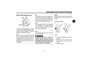
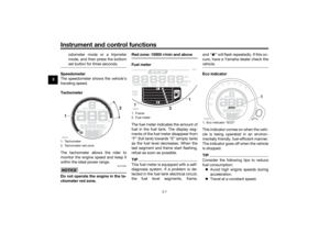
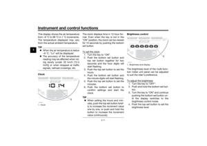
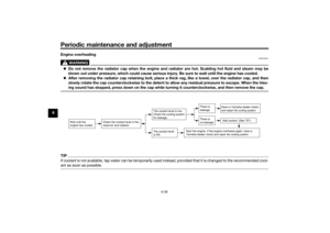
the vehicle has traveled 1 km (0.6 mi).Coolant temperatureThis display shows the coolant tem-
perature from 40 ┬░C to 116 ┬░C in 1 ┬░C
increments.
If the message ŌĆ£HIŌĆØ flashes, stop the
vehicle, then stop the engine and let
the it cool. (See page 6-39.)
TIP’ü¼When the coolant temperature is
below 40 ┬░C, ŌĆ£LoŌĆØ will be dis-
played.
’ü¼The coolant temperature varies
with changes in the weather and
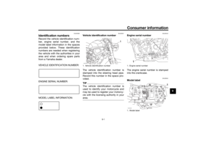
engine load.Air temperature
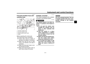
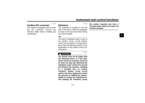
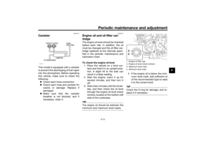
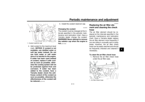
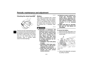
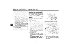
1. Average fuel consumption displayZAUM1336
1
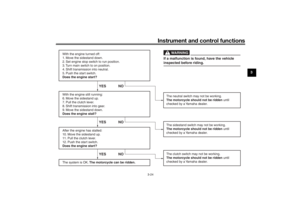
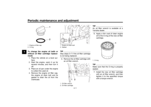
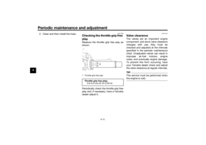
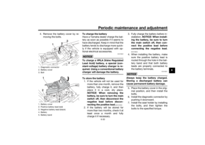
1. Coolant temperature displayZAUM1337
1
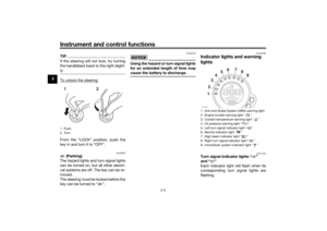
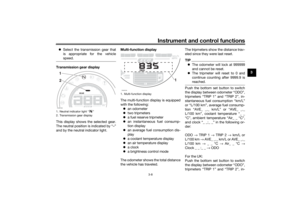
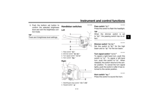
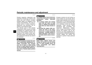
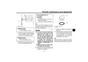
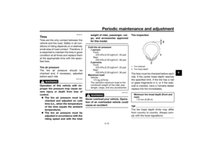
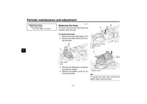
1. Air temperature displayZAUM1338
1
UBU3E1E0.book Page 10 Monday, June 4, 2018 5:20 PM
Page 26 of 98

Instrument and control functions
3-11
3This display shows the air temperature
from ŌĆō9 ┬░C to 99 ┬░C in 1 ┬░C increments.
The temperature displayed may vary
from the actual ambient temperature.
TIP’ü¼When the air temperature is below
ŌĆō9 ┬░C, ŌĆ£LoŌĆØ will be displayed.
’ü¼The accuracy of the temperature
reading may be affected when rid-
ing slowly (under 20 km/h [12.5
mi/h]) or when stopped at traffic
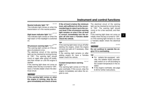
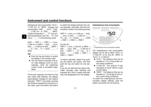
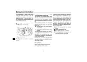
signals, railroad crossings, etc.ClockThe clock displays time in 12-hour for-
mat. Even when the key is not in the
ŌĆ£ONŌĆØ position, the clock can be viewed
for 10 seconds by pushing the bottom
set button.
To set the clock
1. Turn the key to ŌĆ£ONŌĆØ.
2. Push the bottom set button and
top set button together for two
seconds and the hour digits will
start flashing.
3. Push the top set button to set the
hours.
4. Push the bottom set button and
the minute digits will start flashing.
5. Push the top set button to set the
minutes.
6. Push the bottom set button to
confirm settings and start the
clock.TIP’ü¼When setting the hours and min-
utes, push the top set button brief-
ly to increase the increment value
one by one, or push and hold the
button to increase the increment
value continuously.
Brightness control
The brightness level of the multi-func-
tion meter unit panel can be adjusted
to suit the riderŌĆÖs preference.
To adjust the brightness1. Turn the key to ŌĆ£OFFŌĆØ.
2. Push and hold the bottom set but-
ton.
3. Turn the key to ŌĆ£ONŌĆØ and continue
pushing the bottom set button un-
til the display switches to the
brightness control mode.
4. Push the top set button to set the
brightness level.
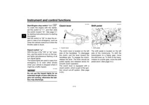
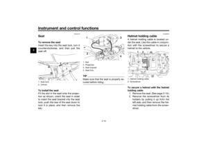
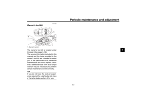
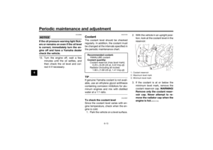
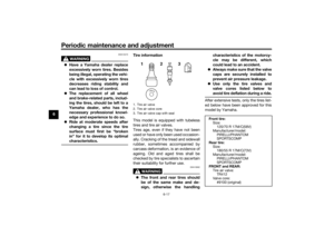
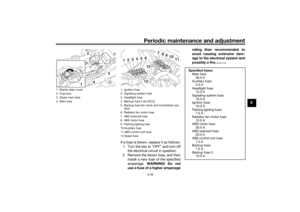
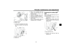
1. ClockZAUM1339
1
1. Brightness level displayZAUM1341
1
UBU3E1E0.book Page 11 Monday, June 4, 2018 5:20 PM
Page 27 of 98

Instrument and control functions
3-12
3 5. Push the bottom set button to
confirm the selected brightness
level and exit the brightness con-
trol mode.
TIPThere are 6 brightness level settings.
EAU1234M
Handlebar switchesLeft
Right
EAU12352
Pass switch ŌĆ£ ŌĆØ
Press this switch to flash the headlight.TIPWhen the dimmer switch is set
to ┼Į, the passing switch has no ef-
fect.
EAU12401
Dimmer switch ŌĆ£ / ŌĆØ
Set this switch to ŌĆ£ ŌĆØ for the high
beam and to ŌĆ£ ŌĆØ for the low beam.
EAU12461
Turn signal switch ŌĆ£ / ŌĆØ
To signal a right-hand turn, push this
switch to ŌĆ£ ŌĆØ. To signal a left-hand
turn, push this switch to ŌĆ£ ŌĆØ. When
released, the switch returns to the cen-
ter position. To cancel the turn signal
lights, push the switch in after it has re-
turned to the center position.
EAU12501
Horn switch ŌĆ£ ŌĆØ
Press this switch to sound the horn.
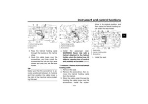
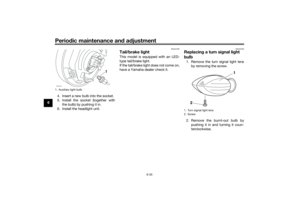
1. Pass switch ŌĆ£ ŌĆØ
2. Dimmer switch ŌĆ£ / ŌĆØ
3. Turn signal switch ŌĆ£ / ŌĆØ
4. Horn switch ŌĆ£ ŌĆØ
1. Start/Engine stop switch ŌĆ£ / / ŌĆØ
2. Hazard switch ŌĆ£ ŌĆØ
2341
12
UBU3E1E0.book Page 12 Monday, June 4, 2018 5:20 PM
Page 28 of 98

Instrument and control functions
3-13
3
EAU68270
Start/Engine stop switch ŌĆ£ / / ŌĆØ
To crank the engine with the starter,
set this switch to ŌĆ£ ŌĆØ, and then slide
the switch toward ŌĆ£ ŌĆØ. See page 5-1
for starting instructions prior to starting
the engine.
Set this switch to ŌĆ£ ŌĆØ to stop the en-
gine in case of an emergency, such as
when the vehicle overturns or when the
throttle cable is stuck.
EAU12735
Hazard switch ŌĆ£ ŌĆØ
With the key in the ŌĆ£ONŌĆØ or ŌĆ£ ŌĆØ posi-
tion, use this switch to turn on the haz-
ard lights (simultaneous flashing of all
turn signal lights).
The hazard lights are used in case of an
emergency or to warn other drivers
when your vehicle is stopped where it
might be a traffic hazard.NOTICE
ECA10062
Do not use the hazard lights for an
extended length of time with the en-
gine not running, otherwise the bat-
tery may discharge.
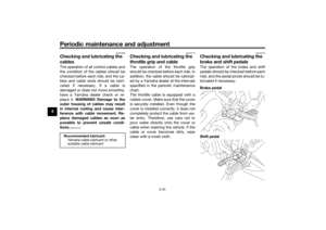
EAU12822
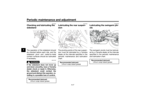
Clutch leverThe clutch lever is located on the left
side of the handlebar. To disengage
the clutch, pull the lever toward the
handlebar grip. To engage the clutch,
release the lever. The lever should be
pulled rapidly and released slowly for
smooth clutch operation.
The clutch lever is equipped with a
clutch switch, which is part of the igni-
tion circuit cut-off system. (See page
3-23.)
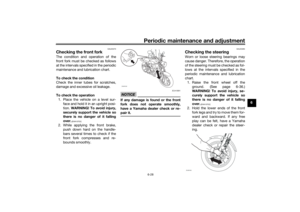
EAU12874
Shift pedalThe shift pedal is located on the left
side of the motorcycle. To shift the
transmission to a higher gear, move
the shift lever up. To shift to the trans-
mission to a lower gear, move the shift
pedal down. (See page 5-2.)
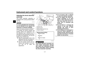
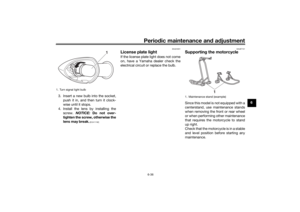
1. Clutch lever
1
1. Shift pedalZAUM1342
1
UBU3E1E0.book Page 13 Monday, June 4, 2018 5:20 PM
Page 29 of 98

Instrument and control functions
3-14
3
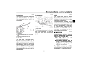
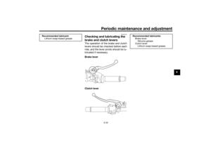
EAU26826
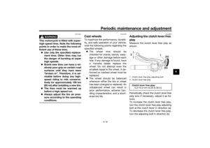
Brake leverThe brake lever is located on the right
side of the handlebar. To apply the
front brake, pull the lever toward the
throttle grip.
The brake lever is equipped with a
brake lever position adjusting dial. To
adjust the distance between the brake
lever and the throttle grip, slightly pull
the brake lever away from the throttle
grip and rotate the adjusting dial. Make
sure the setting number on the adjust-
ing dial aligns with the match mark on
the brake lever.
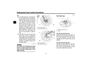
EAU12944
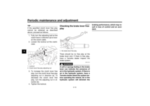
Brake pedalThe brake pedal is located on the right
side of the motorcycle. To apply the
rear brake, press down on the brake
pedal.
EAU63040
ABSThe Yamaha ABS (Anti-lock Brake
System) features a dual electronic con-
trol system, which acts on the front and
rear brakes independently.
Operate the brakes with ABS as you
would conventional brakes. If the ABS
is activated, a pulsating sensation may
be felt at the brake lever or brake ped-
al. In this situation, continue to apply
the brakes and let the ABS work; do
not ŌĆ£pumpŌĆØ the brakes as this will re-
duce braking effectiveness.
WARNING
EWA16051
Always keep a sufficient distance
from the vehicle ahead to match the
riding speed even with ABS.
’ü¼The ABS performs best with
long braking distances.
’ü¼On certain surfaces, such as
rough or gravel roads, the brak-
ing distance may be longer with
the ABS than without.The ABS is monitored by an ECU,
which will revert the system to conven-
tional braking if a malfunction occurs.
1. Brake lever
2. Distance between brake lever and throttle
grip
3. Brake lever position adjusting dial
4. ŌĆ£ ŌĆØ mark
1
2
4 3
1. Brake pedal
1
UBU3E1E0.book Page 14 Monday, June 4, 2018 5:20 PM
Page 30 of 98

Instrument and control functions
3-15
3
TIP’ü¼The ABS performs a self-diagno-
sis test each time the vehicle first
starts off after the key is turned to
ŌĆ£ONŌĆØ and the vehicle has traveled
at a speed of 10 km/h (6 mi/h) or
higher. During this test, a ŌĆ£click-
ingŌĆØ noise can be heard from the
hydraulic control unit, and if the
brake lever or brake pedal is even
slightly applied, a vibration can be
felt at the lever and pedal, but
these do not indicate a malfunc-
tion.
’ü¼This ABS has a test mode which
allows the owner to experience
the pulsation at the brake lever or
brake pedal when the ABS is op-
erating. However, special tools are
required, so please consult your
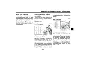
Yamaha dealer.NOTICE
ECA20100
Be careful not to damage the wheel
sensor or wheel sensor rotor; other-
wise, improper performance of the
ABS will result.
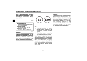
EAU13076
Fuel tank capTo open the fuel tank cap
Open the fuel tank cap lock cover, in-
sert the key into the lock, and then turn
it 1/4 turn clockwise. The lock will be
released and the fuel tank cap can be
opened.
To close the fuel tank cap
With the key still inserted in the lock,
push down the fuel tank cap. Turn the
key 1/4 turn counterclockwise, remove
it, and then close the lock cover.
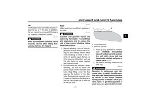
1. Front wheel sensor
2. Front wheel sensor rotor
1. Rear wheel sensor
2. Rear wheel sensor rotor
1
2
12
1. Fuel tank cap lock cover
2. Unlock.
1
2
UBU3E1E0.book Page 15 Monday, June 4, 2018 5:20 PM
Page 31 of 98

Instrument and control functions
3-16
3
TIPThe fuel tank cap cannot be closed un-
less the key is in the lock. In addition,
the key cannot be removed if the cap is
not properly closed and locked.
WARNING
EWA11092
Make sure that the fuel tank cap is
properly closed after filling fuel.
Leaking fuel is a fire hazard.
EAU13222
FuelMake sure there is sufficient gasoline in
the tank.
WARNING
EWA10882
Gasoline and gasoline vapors are
extremely flammable. To avoid fires
and explosions and to reduce the
risk of injury when refueling, follow
these instructions.1. Before refueling, turn off the en-
gine and be sure that no one is sit-
ting on the vehicle. Never refuel
while smoking, or while in the vi-
cinity of sparks, open flames, or
other sources of ignition such as
the pilot lights of water heaters
and clothes dryers.
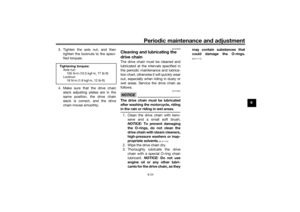
2. Do not overfill the fuel tank. When
refueling, be sure to insert the
pump nozzle into the fuel tank filler
hole. Stop filling when the fuel
reaches the bottom of the filler
tube. Because fuel expands when
it heats up, heat from the engine or
the sun can cause fuel to spill out
of the fuel tank.3. Wipe up any spilled fuel immedi-
ately. NOTICE: Immediately
wipe off spilled fuel with a clean,
dry, soft cloth, since fuel may
deteriorate painted surfaces or
plastic parts.
[ECA10072]
4. Be sure to securely close the fuel
tank cap.
WARNING
EWA15152
Gasoline is poisonous and can
cause injury or death. Handle gaso-
line with care. Never siphon gasoline
by mouth. If you should swallow
some gasoline or inhale a lot of gas-
oline vapor, or get some gasoline in
your eyes, see your doctor immedi-1. Fuel tank filler tube
2. Maximum fuel level
2
1
UBU3E1E0.book Page 16 Monday, June 4, 2018 5:20 PM
Page 32 of 98

Instrument and control functions
3-17
3ately. If gasoline spills on your skin,
wash with soap and water. If gaso-
line spills on your clothing, change
your clothes.
EAU75300
NOTICE
ECA11401
Use only unleaded gasoline. The use
of leaded gasoline will cause severe
damage to internal engine parts,
such as the valves and piston rings,
as well as to the exhaust system.
TIP’ü¼This mark identifies the recom-
mended fuel for this vehicle as
specified by European regulation
(EN228).
’ü¼Check that gasoline nozzle has
the same identifier when fueling.Your Yamaha engine has been de-
signed to use premium unleaded gas-
oline with a research octane number of
95 or higher. If knocking (or pinging)
occurs, use a gasoline of a different
brand. Use of unleaded fuel will extend
spark plug life and reduce mainte-
nance costs.Gasohol
There are two types of gasohol: gaso-
hol containing ethanol and that con-
taining methanol. Gasohol containing
ethanol can be used if the ethanol con-
tent does not exceed 10% (E10). Gas-
ohol containing methanol is not
recommended by Yamaha because it
can cause damage to the fuel system
or vehicle performance problems.
Recommended fuel:
Premium unleaded gasoline (Gaso-
hol [E10] acceptable)
Fuel tank capacity:
14 L (3.7 US gal, 3.1 Imp.gal)
Fuel reserve amount:
2.7 L (0.71 US gal, 0.59 Imp.gal)
E5
E10
UBU3E1E0.book Page 17 Monday, June 4, 2018 5:20 PM