Page 73 of 116
Periodic maintenance and adjustment
7-10
7 4. If the engine oil is below the mini-
mum level mark, add sufficient oil
of the recommended type to raise
it to the correct level.
To change the engine oil (with or
without oil filter element replace-
ment)
1. Start the engine, warm it up for
several minutes, and then turn it
off.
2. Place an oil pan under the engine
to collect the used oil.
3. Remove the engine oil filler cap
and its O-ring, and then remove
the engine oil drain bolt and its
gasket to drain the oil from the
crankcase.
4. Check the O-ring for damage, and
replace it if necessary.
TIP
Skip steps 5…7 if the oil filter element is
not being replaced.
5. Remove the oil filter element cover
by removing the bolts.
6. Remove and replace the oil filter
element and O-ring.
1. Engine oil filler cap
2. O-ring
1
2
1. Engine oil drain bolt
2. Gasket
1. Bolt
2. Oil filter element cover
12
2 1
UBY3E0E0.book Page 10 Friday, September 15, 2017 3:59 PM
Page 74 of 116

Periodic maintenance and adjustment
7-11
77. Install the oil filter element cover
by installing the bolts, then tight-
ening them to the specified
torque.TIP
Make sure that the O-ring is properly
seated.
8. Install the engine oil drain bolt and
its new gasket, and then tighten
the bolt to the specified torque.
9. Refill with the specified amount of
the recommended engine oil.
TIP
Be sure to wipe off spilled oil on any
parts after the engine and exhaust sys-
tem have cooled down.
NOTICE
ECA24060
Make sure that no foreign material
enters the crankcase.
10. Install and tighten the oil filler cap
and its O-ring.
11. Start the engine, and then let it idle
for several minutes while checking
it for oil leakage. If oil is leaking,
immediately turn the engine off
and check for the cause.
12. Turn the engine off, and then
check the oil level and correct it if
necessary.
13. Reset the oil change indicator.
(See page 4-7.)
TIP
If the engine oil is changed before the
oil change indicator comes on (i.e. be-
fore the periodic oil change interval has
been reached), the indicator must be
reset after the oil change for the next
periodic oil change to be indicated at
the correct time.
1. Oil filter element
2. O-ring
Tightening torque:
Oil filter element cover bolt:
10 N·m (1.0 kgf·m, 7.4 lb·ft)
Tightening torque:
Engine oil drain bolt:
20 N·m (2.0 kgf·m, 15 lb·ft)
Recommended engine oil:
See page 9-1.
Oil quantity:
Oil change:
1.50 L (1.59 US qt, 1.32 Imp.qt)
With oil filter removal:
1.60 L (1.69 US qt, 1.41 Imp.qt)
1
2
UBY3E0E0.book Page 11 Friday, September 15, 2017 3:59 PM
Page 75 of 116

Periodic maintenance and adjustment
7-12
7
EAU20067
Final transmission oil
The final transmission case must be
checked for oil leakage before each
ride. If any leakage is found, have a
Yamaha dealer check and repair the
scooter. In addition, the final transmis-
sion oil must be changed as follows at
the intervals specified in the periodic
maintenance and lubrication chart.
1. Start the engine, warm up the final
transmission oil by riding the
scooter for several minutes, and
then stop the engine.
2. Place the scooter on the center-
stand.
3. Place an oil pan under the final
transmission case to collect the
used oil.
4. Remove the final transmission oil
filler cap and its O-ring from the fi-
nal transmission case.
5. Remove the final transmission oil
drain bolt and its gasket to drain
the oil from the final transmission
case.6. Install the final transmission oil
drain bolt and its new gasket, and
then tighten the bolt to the speci-
fied torque.
7. Refill with the specified amount of
the recommended final transmis-
sion oil. WARNING! Make sure
that no foreign material enters
the final transmission case.
Make sure that no oil gets on
the tire or wheel.
[EWA11312]
8. Install the final transmission oil fill-
er cap and its new O-ring, and
then tighten the oil filler cap.
9. Check the final transmission case
for oil leakage. If oil is leaking,
check for the cause.
1. Final transmission oil filler cap
2. O-ring
1
2
1. Final transmission oil drain bolt
2. Gasket
Tightening torque:
Final transmission oil drain bolt:
20 N·m (2.0 kgf·m, 15 lb·ft)
Recommended final transmission
oil:
See page 9-1.
Oil quantity:
0.20 L (0.21 US qt, 0.18 Imp.qt)
12
UBY3E0E0.book Page 12 Friday, September 15, 2017 3:59 PM
Page 76 of 116

Periodic maintenance and adjustment
7-13
7
EAU20071
Coolant
The coolant level should be checked
before each ride. In addition, the cool-
ant must be changed at the intervals
specified in the periodic maintenance
and lubrication chart.
EAU78580To check the coolant level
1. Place the vehicle on the center-
stand.
TIP
The coolant level must be
checked on a cold engine since
the level varies with engine tem-
perature.
Make sure that the vehicle is posi-
tioned straight up when checking
the coolant level. A slight tilt to the
side can result in a false reading.
2. Check the coolant level through
the check window.
TIP
The coolant should be between the
minimum and maximum level marks.
3. If the coolant is at or below the
minimum level mark, remove the
left floorboard mat by pulling it up.
4. Remove the coolant reservoir cov-
er.
5. Remove the coolant reservoir cap,
add coolant to the maximum level
mark, and then install the reservoir
cap. WARNING! Remove only
the coolant reservoir cap. Never
attempt to remove the radiator
cap when the engine is hot.
[EWA15162] NOTICE: If coolant is not
available, use distilled water or
soft tap water instead. Do not
use hard water or salt water
since it is harmful to the engine.
If water has been used instead
of coolant, replace it with cool-
ant as soon as possible, other-
wise the cooling system will not
1. Coolant level check window
2. Maximum level mark
3. Minimum level mark
1
2
3
1. Floorboard mat
1. Coolant reservoir cover
1
1
UBY3E0E0.book Page 13 Friday, September 15, 2017 3:59 PM
Page 77 of 116

Periodic maintenance and adjustment
7-14
7 be protected against frost and
corrosion. If water has been
added to the coolant, have a
Yamaha dealer check the anti-
freeze content of the coolant as
soon as possible, otherwise the
effectiveness of the coolant will
be reduced.
[ECA10473]
6. Install the coolant reservoir cover.
7. Place the left floorboard mat in the
original position and push it down-
ward to secure it.
EAU33032Changing the coolant
The coolant must be changed at the in-
tervals specified in the periodic mainte-
nance and lubrication chart. Have a
Yamaha dealer change the coolant.
WARNING! Never attempt to remove
the radiator cap when the engine is
hot.
[EWA10382]EAU78574
Air filter and V-belt case air fil-
ter elements
The air filter element and the sub air fil-
ter element should be replaced, and
the pre air filter element and the V-belt
case air filter element should be
cleaned at the intervals specified in the
periodic maintenance and lubrication
chart. Service the air filter elements
more frequently if you are riding in un-
usually wet or dusty areas. The air filter
check hose must be frequently
checked and cleaned if necessary.
Cleaning the air filter check hose
1. Check the hose on the rear side of
the air filter case for accumulated
dirt or water.
2. If dirt or water is visible, remove
the hose from the clamp, clean it,
and then install it.
TIP
If dirt or water was found in the check
hose, be sure to check the air filter ele-
ment for excessive dirt or damage and
replace it if necessary.
1. Coolant reservoir cap
Coolant reservoir capacity (up to
the maximum level mark):
0.18 L (0.19 US qt, 0.16 Imp.qt)
1
1. Air filter check hose
1
UBY3E0E0.book Page 14 Friday, September 15, 2017 3:59 PM
Page 78 of 116

Periodic maintenance and adjustment
7-15
7Replacing the air filter element and
sub air filter element and cleaning
the pre air filter element
1. Place the vehicle on the center-
stand.
2. Remove the rubber plugs.
3. Remove the air filter case cover by
removing the screws.
4. Pull the air filter element and sub
air filter element out.5. Insert a new sub air filter element
into the air filter case cover.
6. Insert a new air filter element into
the air filter case. NOTICE: Make
sure that the air filter element is
properly seated in the air filter
case. The engine should never
be operated without the air filter
element installed, otherwise the
piston(s) and/or cylinder(s) may
become excessively worn.
[ECA10482]
7. Pull the pre air filter element out,
and then blow out the dirt with
compressed air as shown.
1. Rubber plug
1. Air filter case cover
2. Screw
1
1
2
2
2 2
1. Air filter element
1. Sub air filter element
2. Air filter case cover
1
1
2
UBY3E0E0.book Page 15 Friday, September 15, 2017 3:59 PM
Page 79 of 116
Periodic maintenance and adjustment
7-16
7
8. Check the pre air filter element for
damage, and replace it if neces-
sary.
9. Insert the pre air filter element into
the air filter case cover.
10. Install the air filter case cover by
installing the screws.
TIP
The long screw should be installed as
shown.
11. Install the rubber plugs.
Cleaning the V-belt case air filter el-
ement
1. Place the vehicle on the center-
stand.
2. Remove the air filter case cover.
(See the previous section.)
3. Remove the V-belt case cover
screws.
4. Remove the air filter case bolts.
1. Pre air filter element
2. Air filter case cover
1
2
1. Long screw
1. Screw
1
1
1
UBY3E0E0.book Page 16 Friday, September 15, 2017 3:59 PM
Page 80 of 116
Periodic maintenance and adjustment
7-17
75. Lift up the air filter case slightly, re-
move the rear wheel sensor lead
from the holder, and then remove
the V-belt case cover.
6. Remove the V-belt case air filter
cover by removing the bolts.7. Remove the air filter element, and
then blow out the dirt with com-
pressed air from the clean side as
shown.
8. Check the V-belt case air filter ele-
ment for damage and replace it if
necessary.
9. Insert the element into the V-belt
case.
10. Install the V-belt case air filter cov-
er by installing the bolts.
11. Install the rear wheel sensor lead
into the holder at the white tape on
the lead as shown.
1. Bolt
1. Rear wheel sensor lead
2. Lead holder
1. V-belt case air filter cover
2. Bolt
1
1
22
1
2
2
1. V-belt case air filter element
1. Clean side
1
1
UBY3E0E0.book Page 17 Friday, September 15, 2017 3:59 PM
 1
1 2
2 3
3 4
4 5
5 6
6 7
7 8
8 9
9 10
10 11
11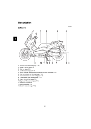 12
12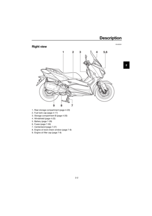 13
13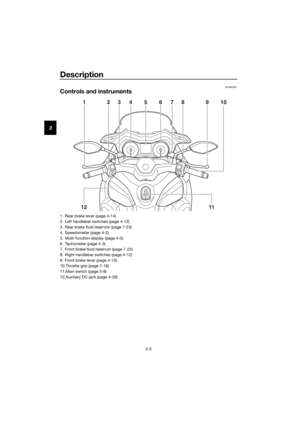 14
14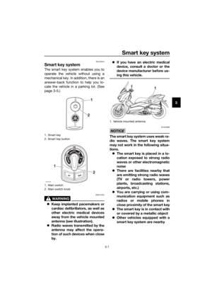 15
15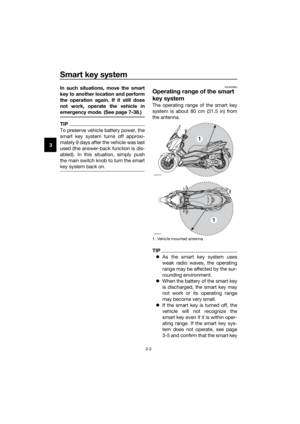 16
16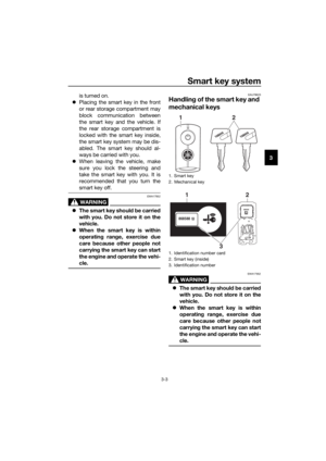 17
17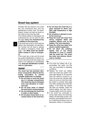 18
18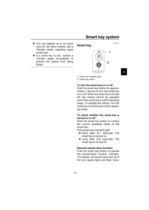 19
19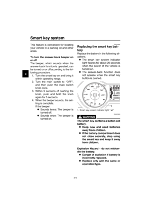 20
20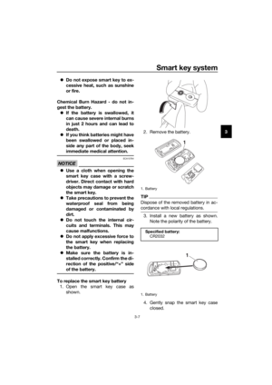 21
21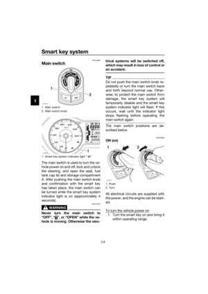 22
22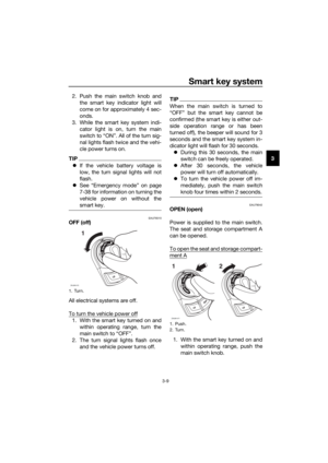 23
23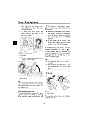 24
24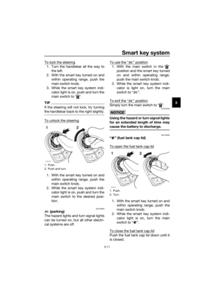 25
25 26
26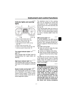 27
27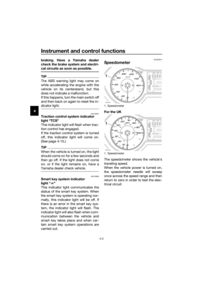 28
28 29
29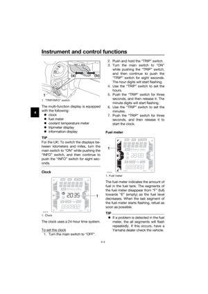 30
30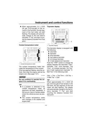 31
31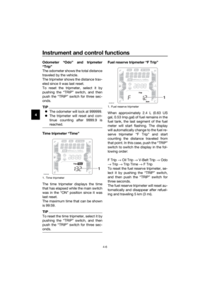 32
32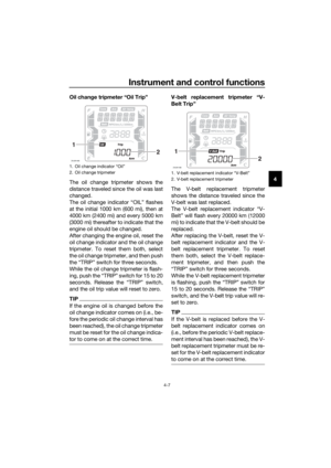 33
33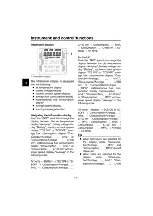 34
34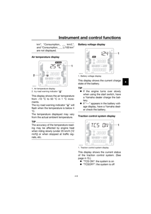 35
35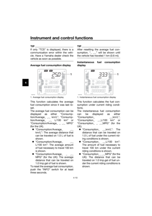 36
36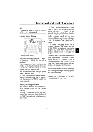 37
37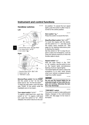 38
38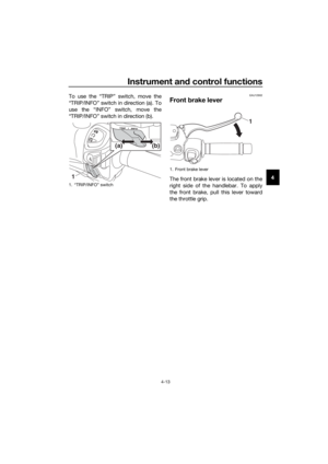 39
39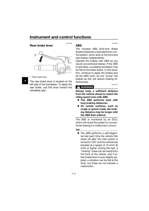 40
40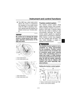 41
41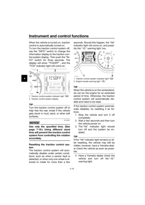 42
42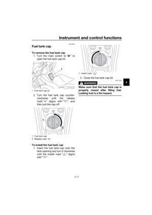 43
43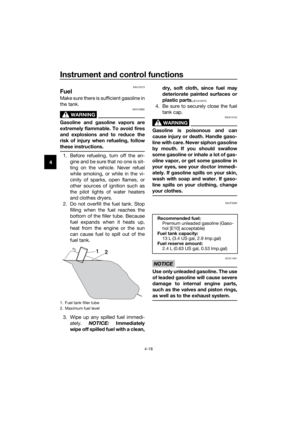 44
44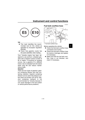 45
45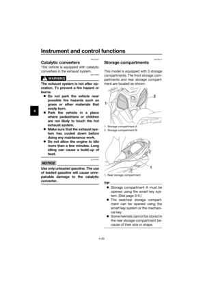 46
46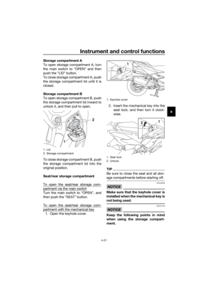 47
47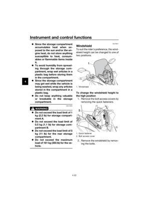 48
48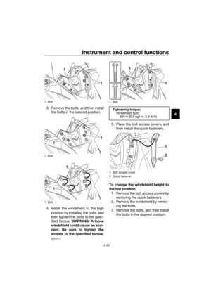 49
49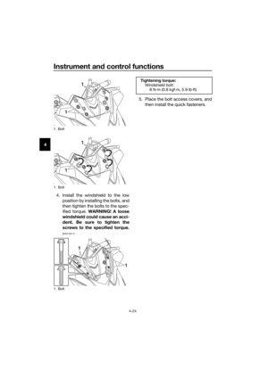 50
50 51
51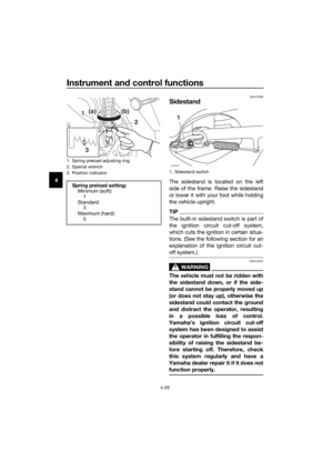 52
52 53
53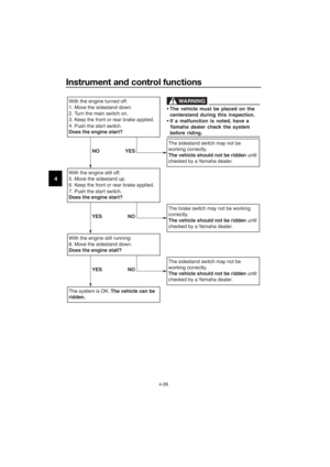 54
54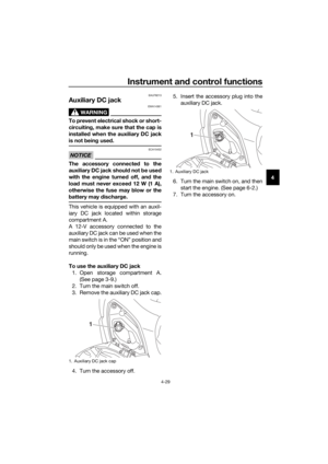 55
55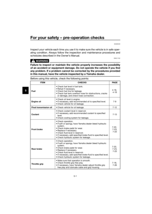 56
56 57
57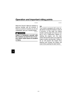 58
58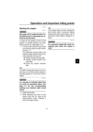 59
59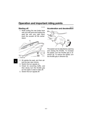 60
60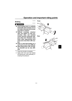 61
61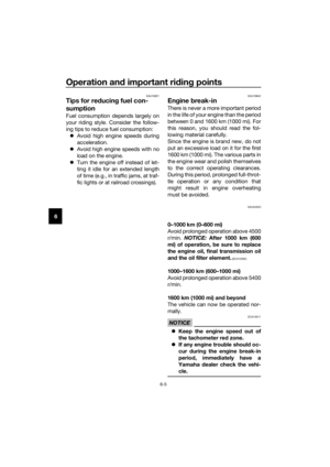 62
62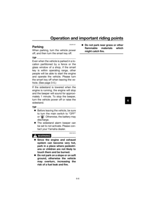 63
63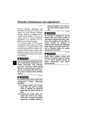 64
64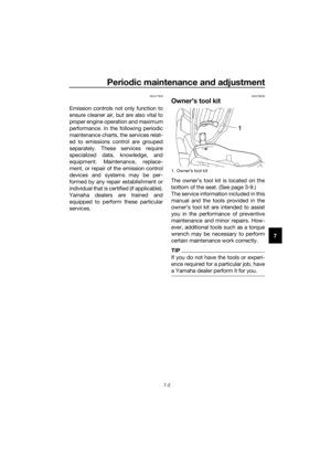 65
65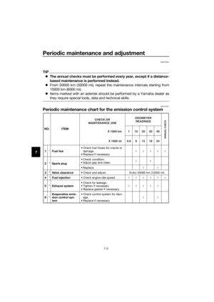 66
66 67
67 68
68 69
69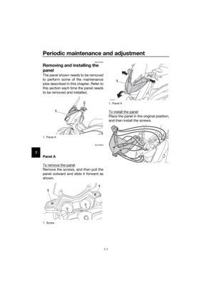 70
70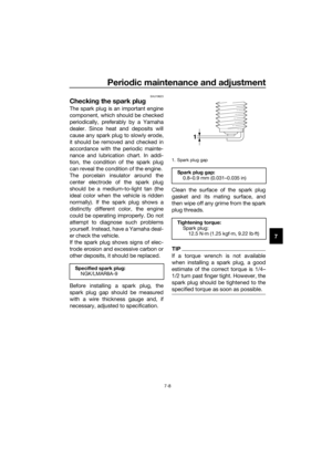 71
71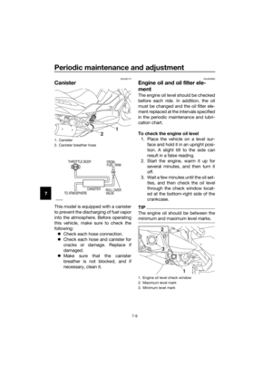 72
72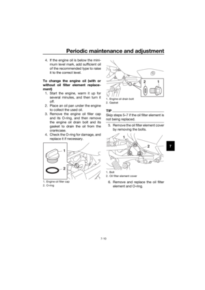 73
73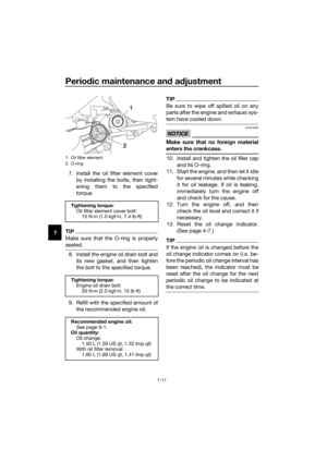 74
74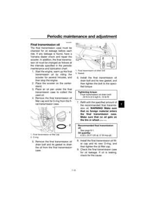 75
75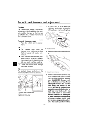 76
76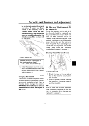 77
77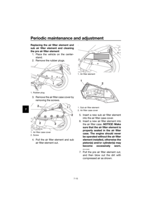 78
78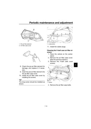 79
79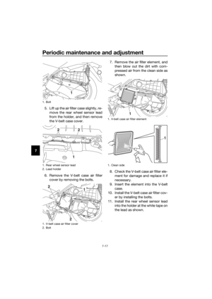 80
80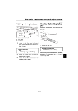 81
81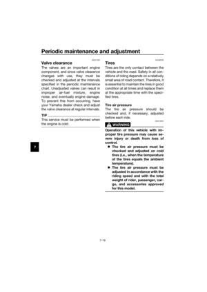 82
82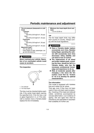 83
83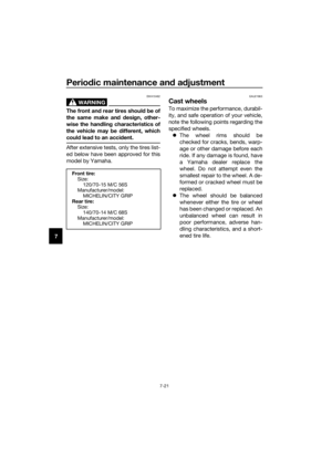 84
84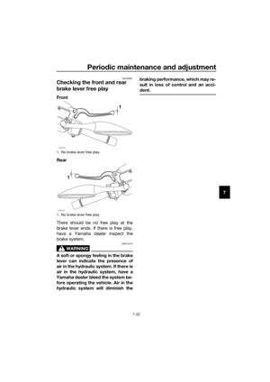 85
85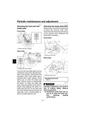 86
86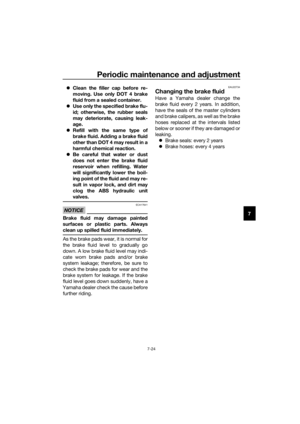 87
87 88
88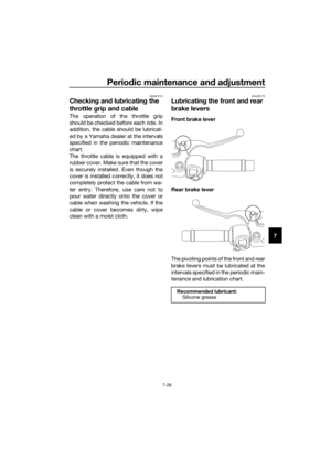 89
89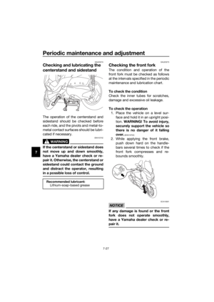 90
90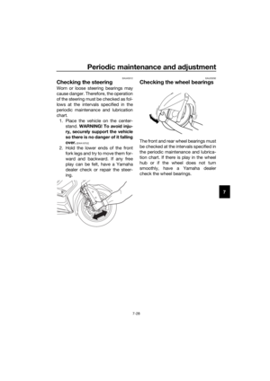 91
91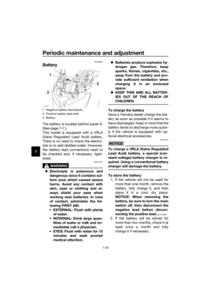 92
92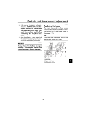 93
93 94
94 95
95 96
96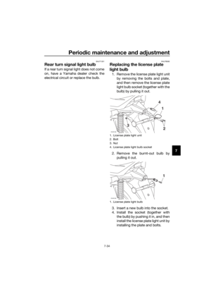 97
97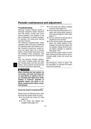 98
98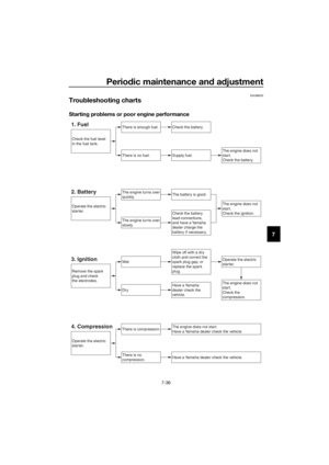 99
99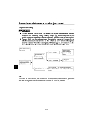 100
100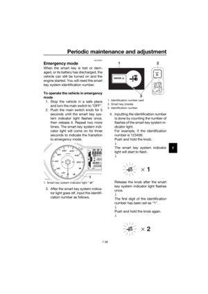 101
101 102
102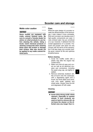 103
103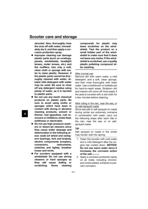 104
104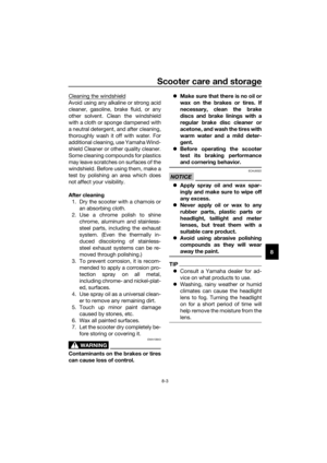 105
105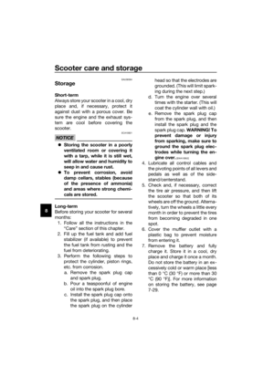 106
106 107
107 108
108 109
109 110
110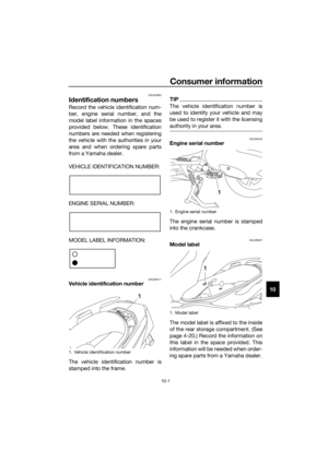 111
111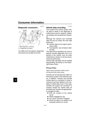 112
112 113
113 114
114 115
115

