Page 49 of 114

Instrument and control functions
3-34
3
Re boun d d ampin g force
The rebound damping force is adjust-
ed on the right front fork leg only.
To increase the rebound damping
force and thereby harden the rebound
damping, turn the adjusting screw in
direction (a). To decrease the rebound
damping force and thereby soften the
rebound damping, turn the adjusting
screw in direction (b).
TIP When adjusting the damping force
settings, turn the adjuster in direc-
tion (a) until it stops, and then
count the turns or clicks in direc-
tion (b).
Although a damping force adjust-
er may turn or click beyond the
stated minimum settings, such
adjustments are ineffective and
may damage the suspension.
When turning a damping force ad-
juster in direction (a), the 0 click
position and the 1 click position
may be the same.
EAU57942
Adjustin g the shock a bsor ber
assem blyThis shock absorber assembly is
equipped with a spring preload adjust-
ing ring and a rebound damping force
adjusting screw.NOTICE
ECA10102
To avoi d d amag ing the mechanism,
d o not attempt to turn beyon d the
maximum or minimum settin gs.Sprin g preloa d
To increase the spring preload and
thereby harden the suspension, turn
the adjusting ring in direction (a). To
decrease the spring preload and there-
by soften the suspension, turn the ad-
justing ring in direction (b).
Sprin g preloa d settin g:
Minimum (soft):
Distance A = 19.0 mm (0.75 in)
Standard:
Distance A = 16.0 mm (0.63 in)
Maximum (hard): Distance A = 4.0 mm (0.16 in)1. Rebound damping force adjusting screw
1
(a)
(b)
Re boun d d ampin g settin g:
Minimum (soft):
12 click(s) in direction (b)
Standard:
7 click(s) in direction (b)
Maximum (hard): 1 click(s) in direction (b)
UB5CE0E0.book Page 34 Wednesday, December 20, 2017 11:08 AM
Page 50 of 114

Instrument and control functions
3-35
3
Align the appropriate notch in the
adjusting ring with the position in-
dicator on the shock absorber.
Use the special wrench and ex-
tension bar in the tool kit to make
this adjustment. Re
boun d d ampin g force
To increase the rebound damping
force and thereby harden the rebound
damping, turn the adjusting screw in
direction (a). To decrease the rebound
damping force and thereby soften the
rebound damping, turn the adjusting
screw in direction (b).
TIP When adjusting the damping force
settings, turn the adjuster in direc-
tion (a) until it stops, and then
count the turns or clicks in direc-
tion (b).
Although a damping force adjust-
er may turn or click beyond the
stated minimum settings, such
adjustments are ineffective and
may damage the suspension.
WARNING
EWA10222
This shock a bsor ber assem bly con-
tains hi ghly pressurize d nitro gen
g as. Rea d an d und erstan d the fol-
lowin g information b efore handlin g
the shock a bsor ber assem bly.
Do not tamper with or attempt
to open the cylin der assem bly.
Do not su bject the shock a b-
sor ber assem bly to an open
flame or other hi gh heat source.
This may cause the unit to ex-
plo de due to excessive gas
pressure.
1. Spring preload adjusting ring
2. Special wrench
3. Extension bar
4. Position indicatorSprin g preloa d setting :
Minimum (soft): 1
Standard: 4
Maximum (hard):
7
7654321
1(b) (a)
4
2
3
1. Rebound damping force adjusting screwRe
boun d d ampin g setting :
Minimum (soft): 3 turn(s) in direction (b)
Standard: 1-1/2 turn(s) in direction (b)
Maximum (hard):
0 turn(s) in direction (b)
1(a)(b)
UB5CE0E0.book Page 35 Wednesday, December 20, 2017 11:08 AM
Page 51 of 114

Instrument and control functions
3-36
3
Do not d eform or damag e the
cylin der in any way. Cylin der
d amag e will result in poor
d ampin g performance.
Do not d ispose of a damag ed or
worn-out shock a bsor ber as-
sem bly yourself. Take the shock
a b sor ber assem bly to a Yamaha
d ealer for any service.
EAU70641
Auxiliary DC connectorThis vehicle is equipped with an auxil-
iary DC connector. Consult your
Yamaha dealer before installing any
accessories.
EAU15306
Si destan dThe sidestand is located on the left
side of the frame. Raise the sidestand
or lower it with your foot while holding
the vehicle upright.TIPThe built-in sidestand switch is part of
the ignition circuit cut-off system,
which cuts the ignition in certain situa-
tions. (See the following section for an
explanation of the ignition circuit cut-
off system.)
WARNING
EWA10242
The vehicle must not be ri dden with
the si destan d d own, or if the si de-
stan d cannot b e properly move d up
(or does not stay up), otherwise the
si destan d coul d contact the groun d
an d d istract the operator, resultin g
in a possib le loss of control.
Yamaha’s ig nition circuit cut-off
system has been desi gne d to assist
the operator in fulfillin g the respon-
si bility of raisin g the sid estand b e-
fore startin g off. Therefore, check
UB5CE0E0.book Page 36 Wednesday, December 20, 2017 11:08 AM
Page 52 of 114
Instrument and control functions
3-37
3 this system reg
ularly and have a
Yamaha dealer repair it if it does not
function properly.
EAU44895
I g nition circuit cut-off systemThis system prevents in-gear engine
starts unless the clutch lever is pulled
and the sidestand is up. Also, it will
stop the running engine should the
sidestand be lowered while the trans-
mission is in gear.
Periodically check the system via the
following procedure.TIP This check is most reliable if per-
formed with a warmed-up engine.
See pages 3-2 and 3-18 for switch
operation information.
UB5CE0E0.book Page 37 Wednesday, December 20, 2017 11:08 AM
Page 53 of 114

Instrument and control functions
3-38
3
With the engine turned off:
1. Move the sidestand down.
2. Set engine stop switch to run position.
3. Turn main switch to on position.
4. Shift transmission into neutral.
5. Push the start switch.
Does the engine start?
With the engine still running:
6. Move the sidestand up.
7. Pull the clutch lever.
8. Shift transmission into gear.
9. Move the sidestand down.
Does the engine stall?
After the engine has stalled:
10. Move the sidestand up.
11. Pull the clutch lever.
12. Push the start switch.
Does the engine start?
The system is OK. The motorcycle can be ridden.
YES NO YES NO YES NO
The neutral switch may not be working.
The motorcycle should not be ridden until
checked by a Yamaha dealer.
The clutch switch may not be working.
The motorcycle should not be ridden until
checked by a Yamaha dealer.The sidestand switch may not be working.
The motorcycle should not be ridden until
checked by a Yamaha dealer.If a malfunction is found, have the vehicle
inspected before riding.
WARNING
UB5CE0E0.book Page 38 Wednesday, December 20, 2017 11:08 AM
Page 54 of 114
Instrument and control functions
3-39
3
EAU49454
Auxiliary DC jackA 12-V accessory connected to the
auxiliary DC jack can be used when the
main switch is on.NOTICE
ECA15432
The accessory connecte d to the
auxiliary DC jack shoul d not b e used
with the en gine turne d off, an d the
loa d must never excee d 24 W (2 A),
otherwise the fuse may blow or the
b attery may d ischarge.To use the auxiliary DC jack
1. Turn the main switch off.
2. Remove the auxiliary DC jack cap.
3. Turn the accessory off. 4. Insert the accessory plug into the
auxiliary DC jack.
5. Turn the main switch on, and start the engine. (See page 5-1.)
6. Turn the accessory on.
WARNING
EWA14361
To prevent electrical shock or short-
circuitin g, make sure that the cap is
installe d when the auxiliary DC jack
is not bein g use d.
1. Auxiliary DC jack cap
1
1. Auxiliary DC jack
1
UB5CE0E0.book Page 39 Wednesday, December 20, 2017 11:08 AM
Page 55 of 114

For your safety – pre-operation checks
4-1
4
EAU15599
Inspect your vehicle each time you use it to make sure the vehicle is in safe operating condition. Always follow the inspection
and maintenance procedures and schedules described in the Owner’s Manual.
WARNING
EWA11152
Failure to inspect or maintain the vehicle properly increases the possibility of an acci dent or equipment damag e.
Do not operate the vehicle if you fin d any pro blem. If a pro blem cannot be corrected b y the proce dures provi ded in
this manual, have the vehicle inspecte d b y a Yamaha dealer.Before using this vehicle, check the following points:
ITEM CHECKS PAGE
Fuel • Check fuel level in fuel tank.
• Refuel if necessary.
• Check fuel line for leakage.
• Check fuel tank overflow hose for obstructions, cracks or damage, and check
hose connection. 3-25, 3-27
En gine oil • Check oil level in engine.
• If necessary, add recommended oil to specified level.
• Check vehicle for oil leakage. 6-11
Coolant • Check coolant level in reservoir.
• If necessary, add recommended coolant to specified level.
• Check cooling system for leakage. 6-13
Front brake • Check operation.
• If soft or spongy, have Yamaha dealer bleed hydraulic system.
• Check brake pads for wear.
• Replace if necessary.
• Check fluid level in reservoir.
• If necessary, add specified brake fluid to specified level.
• Check hydraulic system for leakage. 6-20, 6-21
UB5CE0E0.book Page 1 Wednesday, December 20, 2017 11:08 AM
Page 56 of 114

For your safety – pre-operation checks
4-2
4
Rear brake • Check operation.
• If soft or spongy, have Yamaha dealer bleed hydraulic system.
• Check brake pads for wear.
• Replace if necessary.
• Check fluid level in reservoir.
• If necessary, add specified brake fluid to specified level.
• Check hydraulic system for leakage. 6-20, 6-21
Clutch • Check operation.
• Lubricate cable if necessary.
• Check lever free play.
• Adjust if necessary.
6-19
Throttle g rip • Make sure that operation is smooth.
• Check throttle grip free play.
• If necessary, have Yamaha dealer adjust throttle grip free play and lubricate ca-
ble and grip housing. 6-15, 6-25
Control ca bles • Make sure that operation is smooth.
• Lubricate if necessary. 6-25
Drive chain • Check chain slack.
• Adjust if necessary.
• Check chain condition.
• Lubricate if necessary.
6-23, 6-24
Wheels an d tires •Check for damage.
• Check tire condition and tread depth.
• Check air pressure.
• Correct if necessary.
6-16, 6-18
Brake an d shift pe dals • Make sure that operation is smooth.
• Lubricate pedal pivoting points if necessary. 6-26
Brake an d clutch levers • Make sure that operation is smooth.
• Lubricate lever pivoting points if necessary.
6-26
Centerstan d, si destan d • Make sure that operation is smooth.
• Lubricate pivots if necessary.
6-27
ITEM
CHECKS PAGE
UB5CE0E0.book Page 2 Wednesday, December 20, 2017 11:08 AM
 1
1 2
2 3
3 4
4 5
5 6
6 7
7 8
8 9
9 10
10 11
11 12
12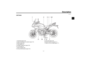 13
13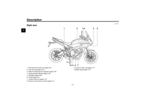 14
14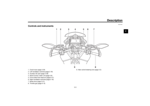 15
15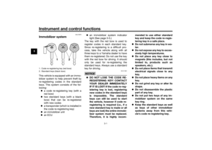 16
16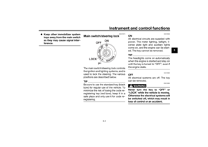 17
17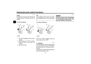 18
18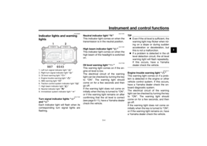 19
19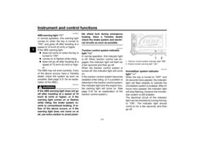 20
20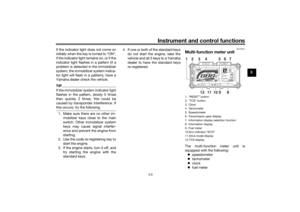 21
21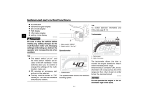 22
22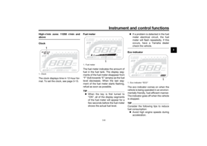 23
23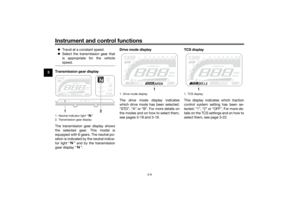 24
24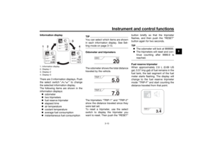 25
25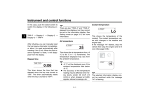 26
26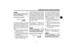 27
27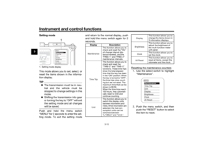 28
28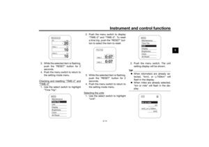 29
29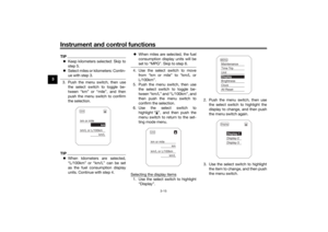 30
30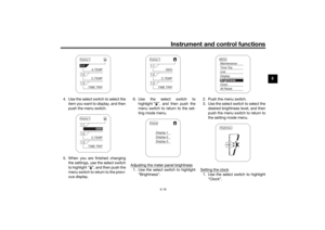 31
31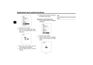 32
32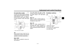 33
33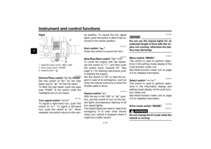 34
34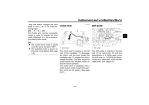 35
35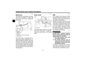 36
36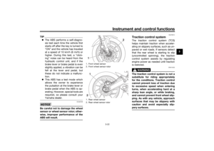 37
37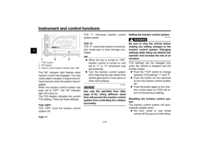 38
38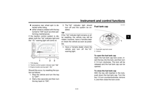 39
39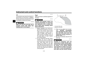 40
40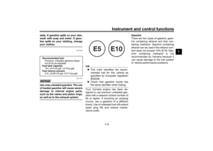 41
41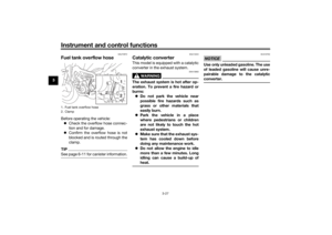 42
42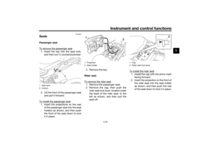 43
43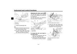 44
44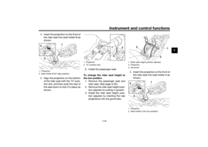 45
45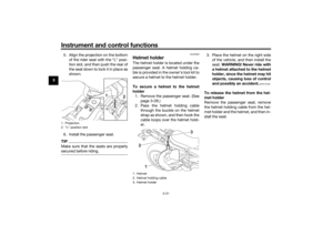 46
46 47
47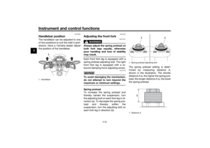 48
48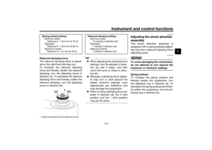 49
49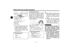 50
50 51
51 52
52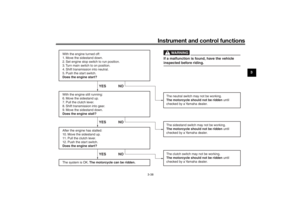 53
53 54
54 55
55 56
56 57
57 58
58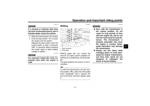 59
59 60
60 61
61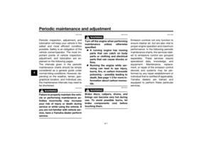 62
62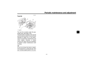 63
63 64
64 65
65 66
66 67
67 68
68 69
69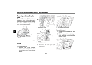 70
70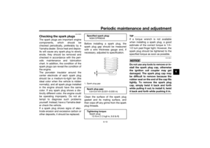 71
71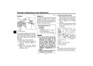 72
72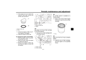 73
73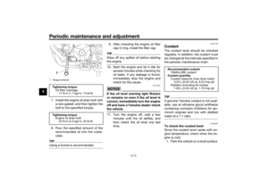 74
74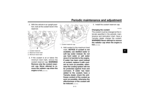 75
75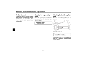 76
76 77
77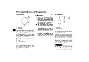 78
78 79
79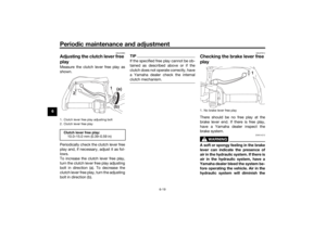 80
80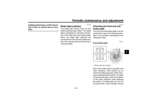 81
81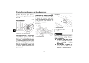 82
82 83
83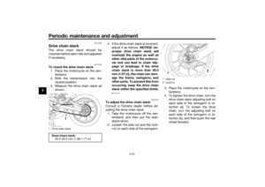 84
84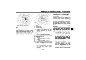 85
85 86
86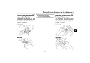 87
87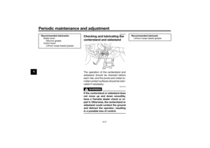 88
88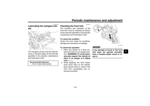 89
89 90
90 91
91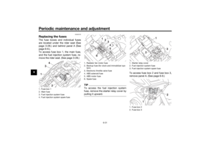 92
92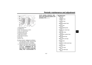 93
93 94
94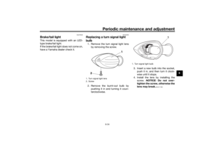 95
95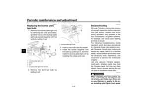 96
96 97
97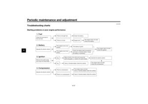 98
98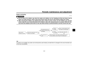 99
99 100
100 101
101 102
102 103
103 104
104 105
105 106
106 107
107 108
108 109
109 110
110 111
111 112
112 113
113
