2018 VOLVO XC90 T8 engine
[x] Cancel search: enginePage 577 of 686

WHEELS AND TIRES
}}
575
7. Connect the electrical cable to the nearest
12 V outlet and start the vehicle.
NOTE
Make sure that none of the vehicle's other 12 V sockets are used while the compressoris running.
WARNING
Never leave children unattended in the vehicle while the engine is running. 8. Start the compressor by moving the switch to
the I (On) position.
WARNING
Never stand next to a tire being inflated with the compressor. If cracks, bulges, etc. form onthe tire, switch off the compressor immedi-ately. The vehicle should not be driven. Callroadside assistance to have the vehicle towedto a workshop for inspection/replacement ofthe tire. Volvo recommends an authorizedworkshop.
NOTE
When the compressor first starts, air pressure may temporarily increase up to 6 bar (88 psi)but should decrease again after approxi-mately 30 seconds.
9. Inflate the tire for 7 minutes.
CAUTION
To help avoid overheating, the compressor should never be used for more than10 minutes at a time.
10. Switch off the compressor and check the
inflation pressure using the air pressure gauge. The inflation pressure should bebetween 1.8 bar (22 psi) and 3.5 bar(51 psi). If the inflation pressure is too high,use the air release valve to release air.
WARNING
If the bottle is not removed in the correct order, sealant could spill out.
WARNING
If pressure falls below 1.8 bar (22 psi), the hole in the tire may be too large. The vehicleshould not be driven. Call roadside assistanceto have the vehicle towed to a workshop forinspection/replacement of the tire. Volvo rec-ommends an authorized workshop.
11. Switch off the compressor and remove the electrical cable.
12. Unscrew the hose from the tire's valve and screw the valve cap back on.
13. Put the protective hose cover onto the hose to help prevent leakage of any residual seal- ing compound. Return the equipment to thecargo compartment.
Page 579 of 686

WHEELS AND TIRES
577
Inflate tires with the compressorincluded in the tire sealing system The vehicle's original tires can be inflated using the compressor in the tire sealing system.
1. The compressor must be switched off. Makesure that the switch is in the 0 (Off) position
and take out the electrical cable and the hose.
2. Unscrew the tire's valve cap and screw the hose's valve connector as far as possibleonto the valve. Be sure the air release valve on the com- pressor's hose is completely closed.
3. Connect the electrical cable to the nearest 12 V outlet and start the vehicle.
WARNING
Inhaling exhaust fumes could lead to serious injury. Never leave the engine running in anenclosed space or a space without sufficientventilation.
WARNING
Never leave children unattended in the vehicle while the engine is running.
4. Start the compressor by moving the switch to the I (On) position.
CAUTION
Risk of overheating. The compressor should not be running for longer than 10 minutes ata time.
5. Inflate the tire to the pressure specified on
the tire pressure decal on the driver's side door pillar. If the inflation pressure is toohigh, use the air release valve to release air.
6. Switch off the compressor. Remove the hose and the electrical cable.
7. Screw the valve cap back onto the tire.
NOTE
• After inflating a tire, always replace the valve cap to help prevent valve damagecaused by gravel, dirt, etc.
• Use plastic valve caps only. Metal capscould corrode and become difficult toremove.
NOTE
The compressor is an electric device. Follow local regulations for disposal.
Related information
• Recommended tire pressure (p. 559)
• Using the tire sealing system (p. 573)
• Tire sealing system (p. 572)
Page 585 of 686

LOADING, STORAGE AND PASSENGER COMPARTMENT
583
Status indicator lightCauseAction
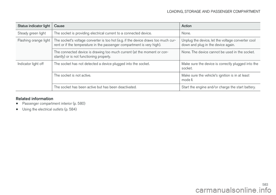
Steady green light The socket is providing electrical current to a connected device. None.
Flashing orange light The socket's voltage converter is too hot (e.g. if the device draws too much cur- rent or if the temperature in the passenger compartment is very high). Unplug the device, let the voltage converter cool down and plug in the device again.
The connected device is drawing too much current (at the moment or con-stantly) or is not functioning properly. None. The device cannot be used in the socket.
Indicator light off The socket has not detected a device plugged into the socket. Make sure the device is correctly plugged into the socket.
The socket is not active. Make sure the vehicle's ignition is in at least mode I.
The socket has been active but has been deactivated. Start the engine and/or charge the start battery.
Related information
• Passenger compartment interior (p. 580)
• Using the electrical outlets (p. 584)
Page 586 of 686

LOADING, STORAGE AND PASSENGER COMPARTMENT
* Option/accessory.
584
Using the electrical outlets
The 12 V outlet can be used for devices intended for this such as MP3 players, coolersand cellular phones. The high-voltage outlet * can be used for devices
intended for this, such as chargers, laptops, etc.
The ignition must be in at least mode I for the
outlets to supply current. The outlets will then be active as long as there is sufficient charge in thestart battery. If the engine is turned off and the vehicle is locked, the outlets will be deactivated. If theengine is turned off and the vehicle remainsunlocked, the sockets will remain active for up to7 minutes.
NOTE
Bear in mind that using the electrical outlets when the engine is off could cause the starterbattery to have too low of a charge level,which could limit other functionality. Accessories connected to the electrical out- lets can be activated even when the vehicleelectrical system is off or if preconditioning isused. For this reason, disconnect plugs whenthey are not in use to prevent the starter bat-tery from becoming discharged.
WARNING
• Do not use accessories with large or heavy plugs – they could damage the out-let or come loose while you are driving.
• Do not use accessories that could causedisruptions to e.g. the vehicle's radioreceiver or electrical system.
• Position the accessory so that there is norisk of it injuring the driver or passengersin the event of heavy braking or a colli-sion.
• Pay attention to connected accessoriesas they can generate heat that could burnpassengers or the interior.
Using 12 V outlets1. Remove the stopper (tunnel console) or fold
down the cover (trunk/cargo compartment)over the socket and plug in the device.
2. Unplug the device and put the stopper back in (tunnel console) or fold up the cover(trunk/cargo compartment) when the socketis not in use or left unattended.
CAUTION
The maximum power is 120 W (10 A) per outlet.
Using high-voltage outletsThe ignition must be in at least mode I for outlets
to supply current. The outlets will then be active as long as there is sufficient charge in the startbattery. 1. Slide down the cover over the outlet and plug in the device. >
The LED 2
light on the outlet will indicate
its status.
2. The outlet is supplying electrical current when the light is glowing steadily green.
3. Disconnect the device by pulling out the plug (do not pull on the cord). Pull up the cover when the outlet is not in use or is left unattended.
CAUTION
The maximum power is 150 W.
WARNING
Do not attempt to alter or repair the high-volt- age outlet on your own. Volvo recommendscontacting an authorized Volvo workshop.
2LED (Light Emitting Diode)
Page 587 of 686

LOADING, STORAGE AND PASSENGER COMPARTMENT
585
WARNING
•Only use accessories that are not dam- aged or malfunctioning. The accessoriesmust be designed for 120 V and 60 Hz,with plugs intended for the outlet. Theaccessories must be CE marked, ULmarked or have an equivalent safetymarking.
• New let outlets, plugs or accessoriescome into contact with water or anotherfluid. Do not touch or use the outlet if itappears damaged or has been in contactwith water or another fluid.
• Do not connect power strips, adapters orextension cords to the outlet has thiscould cause the outlet's safety functionsto malfunction.
• The outlet is equipped with a pet guard.Make sure that no one picks at or dam-ages the outlet in such a way that theguard is disabled. Children should not beleft unsupervised in the vehicle when theoutlet is active.
Failure to follow the above could lead to severe or fatal electrical shocks.
Related information
• Electrical outlets (p. 582)
• Passenger compartment interior (p. 580)
Using the glove compartment
The glove compartment is located on the pas- senger side. The glove compartment can beused to store the Owner's Manual, maps, etc.There is also room for a pen and a card holder.
Glove compartment and opening button on the center console.
The glove compartment is opened by pressing the opening button in the center console.
Locking and unlocking the glove box
The glove compartment can be locked ("private locking") when the vehicle is left at a workshop,hotel, etc. When private locking is activated, thetailgate is also locked.
Using the glove box as a cooled area
The glove compartment can be used to cool e.g. drinks or food. Cooling is possible when the cli- mate system is active (i.e. when the ignition is in mode II or when the engine is running).
The illustration is generic – the design may vary.
Activate cooling
Deactivate cooling
–Activate or deactivate cooling by moving the control as far as possible toward the passen-ger compartment/glove compartment.
Related information
• Passenger compartment interior (p. 580)
• Private Locking (p. 266)
Page 589 of 686

LOADING, STORAGE AND PASSENGER COMPARTMENT
* Option/accessory.587
WARNING
In a head-on collision at a speed of 50 km/h (30 mph), an unsecured object weighing 20kg (44 pounds) can reach a projectile weightequivalent to 1000 kg (2200 pounds).
WARNING
If objects are loaded higher than the upper edge of the side windows, leave a 10 cm (4in.) space between the objects and the win-dow. Objects placed closer to this couldimpede the function of the inflatable curtainconcealed inside the headlining.
WARNING
Always secure the load. Otherwise, it may shift during heavy braking and injure people in thevehicle. Cover sharp edges and sharp corners with something soft. Turn off the engine and apply the parking brake when loading/unloading long objects.Otherwise, it is possible for the load to reachthe gear lever or gear selector and move it toa drive position – which could cause the vehi-cle to begin rolling.
Extra cargo space
The rear seat backrests can be folded down to increase cargo compartment space and simplifyloading. If the rear seat backrests are folded down, make sure that no objects loaded into thevehicle prevent the WHIPS system for the frontseats from functioning correctly.
Raising/lowering the rear end of the vehicle
*
The rear end of the vehicle can be lowered or raised for easier loading or to facilitate attaching a trailer*.
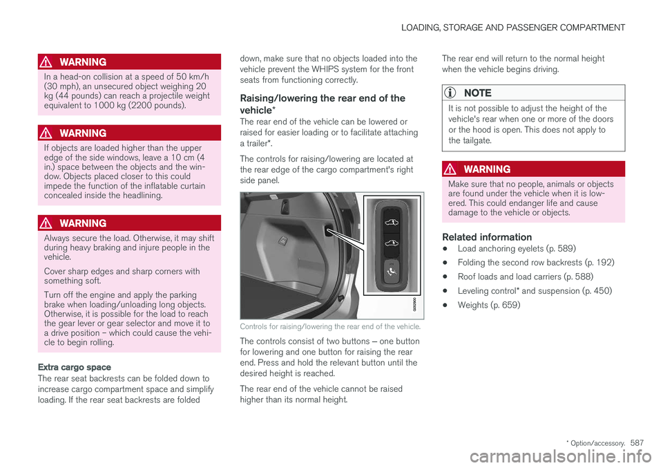
The controls for raising/lowering are located at the rear edge of the cargo compartment's rightside panel.
Controls for raising/lowering the rear end of the vehicle.
The controls consist of two buttons ‒ one button
for lowering and one button for raising the rear end. Press and hold the relevant button until thedesired height is reached. The rear end of the vehicle cannot be raised higher than its normal height. The rear end will return to the normal heightwhen the vehicle begins driving.
NOTE
It is not possible to adjust the height of the vehicle's rear when one or more of the doorsor the hood is open. This does not apply tothe tailgate.
WARNING
Make sure that no people, animals or objects are found under the vehicle when it is low-ered. This could endanger life and causedamage to the vehicle or objects.
Related information
•
Load anchoring eyelets (p. 589)
• Folding the second row backrests (p. 192)
• Roof loads and load carriers (p. 588)
• Leveling control
* and suspension (p. 450)
• Weights (p. 659)
Page 601 of 686

MAINTENANCE AND SERVICE
}}
599
Periodic maintenance helps minimize
emissions
NOTE
•Refer to your Service and Warranty Book- let for a comprehensive service and main-tenance schedule up to 240,000 km(150,000 miles). This program containsinspections and services necessary forthe proper function of your vehicle andincludes components that affect vehicleemissions.
• The Warranty and Service Records Infor-mation booklet also contains detailedinformation concerning the warrantiesthat apply to your vehicle.
On-board Diagnostic SystemOBD II is part of your vehicle's computerized engine management system. It stores diagnosticinformation about your vehicle's emission con-trols. It can light the Check Engine light (MIL) if itdetects an emission control "fault." A "fault" is acomponent or system that is not performingwithin an expected range. A fault may be perma-nent or temporary. OBD II will store a messageabout any fault.
Emission inspection readiness
How do states use OBD II for emission
inspections?
Many states connect a computer directly to a vehicle's OBD II system. The inspector can thenread "faults." In some states, this type of inspec-tion has replaced the tailpipe emission test.
How can my vehicle fail OBD II emission
inspection?
Your vehicle can fail OBD II emission inspection for any of the following reasons:
• If your Check Engine (MIL) light is lit, yourvehicle may fail inspection.
• If your vehicle's Check Engine light was lit,but went out without any action on your part,OBD II will still have a recorded fault. Yourvehicle may pass or fail, depending on theinspection practices in your area.
• If you had recent service that required dis-connecting the battery, OBD II diagnosticinformation may be incomplete and "notready" for inspection. A vehicle that is notready may fail inspection.
How can I prepare for my next OBD II
emission inspection?
• If your Check Engine (MIL) light is lit - or was lit but went out without service, have your vehicle diagnosed and, if necessary, servicedby a qualified Volvo technician.
• If you recently had service for a lit CheckEngine light, or if you had service thatrequired disconnecting the battery, a periodof driving is necessary to bring the OBD IIsystem to "ready" for inspection. Two half-hour trips of mixed stop-and-go/highwaydriving are typically needed to allow OBD II toreach readiness. Your Volvo retailer can pro-vide you with more information on planning atrip.
• Maintain your vehicle in accordance with yourvehicle's maintenance schedule.
Owner maintenancePeriodic maintenance requirements and intervalsare described in your vehicle's Warranty andService Records Information booklet. The following points can be carried out between the normally scheduled maintenance services.
Each time the car is refueled:
•Check the engine oil level.
• Clean the windshield, windshield wipers, headlights, and taillights.
Page 602 of 686

||
MAINTENANCE AND SERVICE
600
Monthly:
•Check cold tire pressure in all tires. Inspect the tires for wear.
• Check that engine coolant and other fluidlevels are between the indicated "min" and"max" markings.
• Clean interior glass surfaces with a glasscleaner and soft paper towels.
• Wipe driver information displays with a softcloth.
• Visually inspect battery terminals for corro-sion. Corrosion may indicate a loose terminalconnector, or a battery near the end of itsuseful service life. Consult your Volvo retailerfor additional information.
As needed:
Wash the car, including the undercarriage, to reduce wear that can be caused by a buildup ofdirt, and corrosion that can be caused by salt res-idues. Clean leaves and twigs from air intake vents at the base of the windshield, and from other placeswhere they may collect.
NOTE
Complete service information for qualified technicians is available online for purchase orsubscription at www.volvotechinfo.com.
Related information
•Vehicle status (p. 602)
• Scheduling service and repairs (p. 603)
• Connecting equipment to the vehicle's data link connector (p. 36)
• Technician certification (p. 37)
• Climate control system service (p. 608)
• Maintenance of the brake system (p. 432)
• Engine compartment overview (p. 609)
Data transfer between vehicle andworkshop over Wi-Fi
Volvo workshops have a designated Wi-Fi net- work for secure data transfer between your vehi-cle and the workshop. Your visit to the workshopwill be easier and more effective when diagnos-tics information and software can be transferredover the workshop's network.
When you arrive at the workshop, your technician can connect your vehicle to the workshop's Wi-Finetwork to perform troubleshooting and down-load software. For this type of communication,the vehicle only connects to the workshop's net-work. The vehicle can only be connected to thedesignated workshop networks, not to any othernetwork, e.g. your home network.
Manual connection to workshop Wi-FiManual connection is usually performed by aservice technician. Because the technician usesthe buttons on your remote key to connect thevehicle, it is important that you bring a key withbuttons when taking the vehicle in to a workshop.Pressing the lock button on the remote key threetimes will connect the vehicle to the workshop'sWi-Fi network. When the car is connected to a Wi-Fi network, the
symbol appears in the center display.