Page 359 of 404
MAINTENANCE AND SERVICING
}}
357
Battery – changing
When changing batteries, be sure to use the correct battery for your vehicle. Consult a Volvoretailer or a trained and qualified Volvo servicetechnician.
Changing
WARNING
Connect and disconnect the positive and neg- ative cables in the correct sequence.
Page 360 of 404

||
MAINTENANCE AND SERVICING
* Option/accessory.
358
Removal
Switch off the ignition, remove the remote key from the ignition slot and wait at least 5 minutesbefore disconnecting the battery so that all infor-mation in the vehicle's electrical system can bestored in the control modules.
Open the clips on the front cover and remove the cover.
Release the rubber molding so that the rear cover is free.
Remove the rear cover by pulling it away.
Detach the black negative cable.
Detach the red positive cable
Detach the ventilation hose from the bat-
tery
Loosen the screw holding the battery
clamp.
Move the battery to the side and lift it up.
WARNING
PROPOSITION 65 WARNING! Battery posts, terminals, and related accesso- ries contain lead and lead compounds, chemi-cals known to the state of California to causecancer and reproductive harm. Wash handsafter handling.
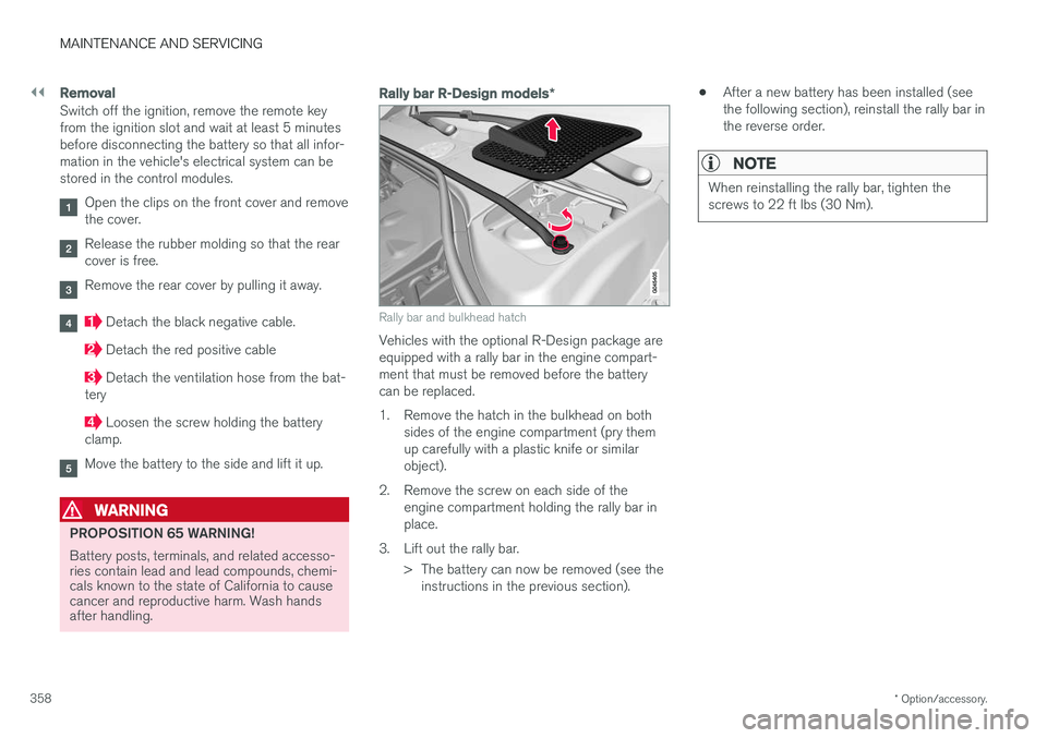
Rally bar R-Design models *
Rally bar and bulkhead hatch
Vehicles with the optional R-Design package are equipped with a rally bar in the engine compart-ment that must be removed before the batterycan be replaced.
1. Remove the hatch in the bulkhead on both
sides of the engine compartment (pry them up carefully with a plastic knife or similarobject).
2. Remove the screw on each side of the engine compartment holding the rally bar inplace.
3. Lift out the rally bar. > The battery can now be removed (see theinstructions in the previous section). •
After a new battery has been installed (seethe following section), reinstall the rally bar inthe reverse order.
NOTE
When reinstalling the rally bar, tighten the screws to 22 ft lbs (30 Nm).
Page 361 of 404

MAINTENANCE AND SERVICING
359
Installation
1. Lower the battery into the battery box.
2. Move the battery inward and to the side untilit reaches the rear edge of the box.
3. Tighten the clamp that secures the battery.
4. Connect the ventilation hose. > Be sure that it is correctly connected tothe battery and the vent in the vehicle's body.
5. Connect the red positive cable.
6. Connect the black negative cable.
7. Press in the rear cover. (See Removal).
8. Reinstall the molding. (See Removal).
9. Reinstall the front cover and secure it with the clips. (See Removal).
Related information
• Battery – handling (p. 355)
• Battery – symbols (p. 354)
Fuses – introduction
The fuses help protect the vehicle's electrical components from overloading.
There are relay/fuseboxes located in the engine compartment, the passenger compartment andthe cargo area. If an electrical component fails to function, this may be due to a blown fuse. The easiest way tosee if a fuse is blown is to remove it. To do so:
1. Pull the fuse straight out. If a fuse is difficult to remove, a special fuse removal tool is
located on the inside of the engine com- partment fusebox cover .
2. From the side, examine the curved metal wire in the fuse to see if it is intact.
If the wire is broken, insert a new fuse of thesame color and amperage (written on the fuse). If fuses burn out repeatedly, have the electrical system inspected by a trained and qualified Volvoservice technician.
WARNING
Never use metal objects or fuses with higher amperage than those stated on the followingpages. Doing so could seriously damage oroverload the vehicle's electrical system.
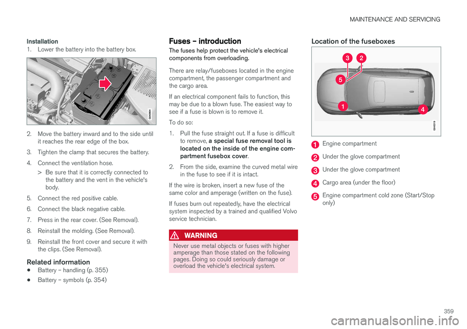
Location of the fuseboxes
Engine compartment
Under the glove compartment
Under the glove compartment
Cargo area (under the floor)
Engine compartment cold zone (Start/Stop only)
Page 370 of 404
||
MAINTENANCE AND SERVICING
368
PosFunction A
Circuit breaker: fusebox A under
the glove compartment (see Fuses – glove compartment(p. 363)) 60
Circuit breaker: fusebox
A under
the glove compartment (see Fuses – glove compartment(p. 363)) 60
Circuit breaker: central electrical module in the cargo area
60
Climate system blower 40
– –
– –
Starter motor relay 30
Internal diode 50
Auxiliary battery 70
Central electrical module: auxili- ary battery reference voltage,auxiliary battery charging point15
Related information
•
Fuses – engine compartment (p. 360)
• Fuses – glove compartment (p. 363) •
Fuses – cargo area/trunk (p. 366)
• Start/Stop – introduction (p. 268)
Page 390 of 404

SPECIFICATIONS
388
Air conditioning – specification and volume
The air conditioning system in your vehicle con- tains the following:
Refrigerant : R134a (HFC134a)
Volume: 1.7 lbs (770 g)
Compressor oil : PAG
Battery specifications If the battery is replaced, replace it with a battery of the same cold start capacity as the original(see the decal on the battery).
General information
WARNING
PROPOSITION 65 WARNING! Battery posts, terminals, and related accesso- ries contain lead and lead compounds, chemi-cals known to the state of California to causecancer and reproductive harm. Wash handsafter handling.
12 volt system with a voltage-regulated alterna- tor. Single pole system in which the chassis andengine block are used as conductors. The nega-tive terminal is connected to the chassis.
Voltage (V) 12 Cold start capacity (Cold CrankingAmperes - CCA) (A) 760
Dimensions, L×W×H in.(mm) 10.9×6.9×7.5
(278×175×190)
Capacity (Ah) 70
Symbols – general information The following tables list the most common warn- ing and indicator lights and symbols and a refer-ence to where more detailed information can befound.
IntroductionThe symbols in the vehicle's various displays are divided into three main categories: • Warning symbols
• Indicator symbols
• Information symbols
The following tables list the most common sym- bols, their meaning and the pages in this manualthat provide more detailed information.
NOTE
Not all of the symbols shown in the related articles are available in all models or on allmarkets. Local variations may occur.
Warning symbol
: The red warning symbol illuminates to
indicate a problem related to safety and/or driva- bility. A message will also appear in the maininstruments panel's display.
Information symbol
: The information symbol illuminates and a
text message is displayed to provide the driver
Page 400 of 404

INDEX
398Rearview mirror
auto-dim function 108
compass 109
Rear window defroster 108
Recalls 28
Recalls, child restraints 50
Refrigerant 388
Refueling 286, 287 fuel filler cap 290
fuel filler door 289, 290
fuel tank volume 386
Registering child restraints 50 Remote control private locking 158
Remote key 152, 153, 154, 156, 159 approach lighting 155
immobilizer 154
key blade 152, 153, 154, 156, 157,158 , 159
locking the vehicle 155
replacing the battery 160
unlocking the vehicle 155
Reporting safety defects 29
Roadside Assistance 25
Road sign information (RSI) 178
Roof loads 146
S
Safety, occupant 28
Safety defects, reporting 29
Safety mode 46Seat belt reminder 32
Seat belts Automatic locking retractor/Emergency
locking retractor 50
buckling 31
maintenance 31
pretensioners 30
reminder 32
reminder warning light 77
securing child restraint systems 52, 54, 56
unbuckling 31
use during pregnancy 33
using 30
Seats, front 83, 84
Sensus 115Service connected service booking 335
Shiftlock 15 override 267
Side door mirrors 106, 107
Side impact airbags 41
Sign information (RSI) 178
Snow chains 315
Snow tires 315, 316
Spare tire 306
Spin control 174, 175SRS 33
Stability system 174, 175, 176 Corner Traction Control (CTC) 174
Engine Drag Control (EDC) 174
indicator light 76
Start/Stop (engine function) 268, 269, 270, 271, 272
Starting the engine 258 remote start 260
with keyless drive 258
Starting the vehicle after a crash (crash mode) 46, 47
Start inhibitor (immobilizer) 154
Steel grid in cargo compartment 150Steering wheel adjusting 91
heated 92
horn 91
keypad 91
Steering wheel paddles 91
Stone chips, touching up 373