Page 6 of 502
In the engine compartment
Fuse box cover Changing fuses
Lever for adjusting the steering column position Steering wheel
Light switch Vehicle lighting
Turn signal and main beam lever Vehicle lighting
With switches and buttons for the driver assist systems Button for driver assist systemsDriver
assist systems
Vents Heating and air conditioning system
Instrument cluster Instrument cluster
With warning and indicator lamps Symbols in instrument cluster
Lever for wipers and washers Wipers
With buttons for operating the menus Instrument cluster
Controls on the multifunction steering wheel:
Operating driver assist systems Operating using the multifunction steering wheelDriver assist
systems
Audio, navigation
Opening the telephone menu or accepting telephone calls
Volume adjustment
Activating voice control (no function in some models)
Horn
Location of the driver front airbag Airbag system
Ignition lock Starting and stopping the engine
Pedals Pedals
Page 130 of 502

WARNING
Incorrect use of turn signals, a failure to use turn signals, or forgetting to switch off a turn signal can
confuse other road users. This could lead to accidents and serious injuries.
Always activate the turn signal in good time when changing lanes and performing overtaking or
turning manoeuvres.
Always switch off the turn signal once the lane change or overtaking or turning manoeuvre has been
completed.
The hazard warning lights also work when the ignition is switched off In an emergency
Some settings can be stored in the user accounts of the personalisation function and therefore
change when the user account changes Personalisation
Vehicle lighting
Switching lights on and off
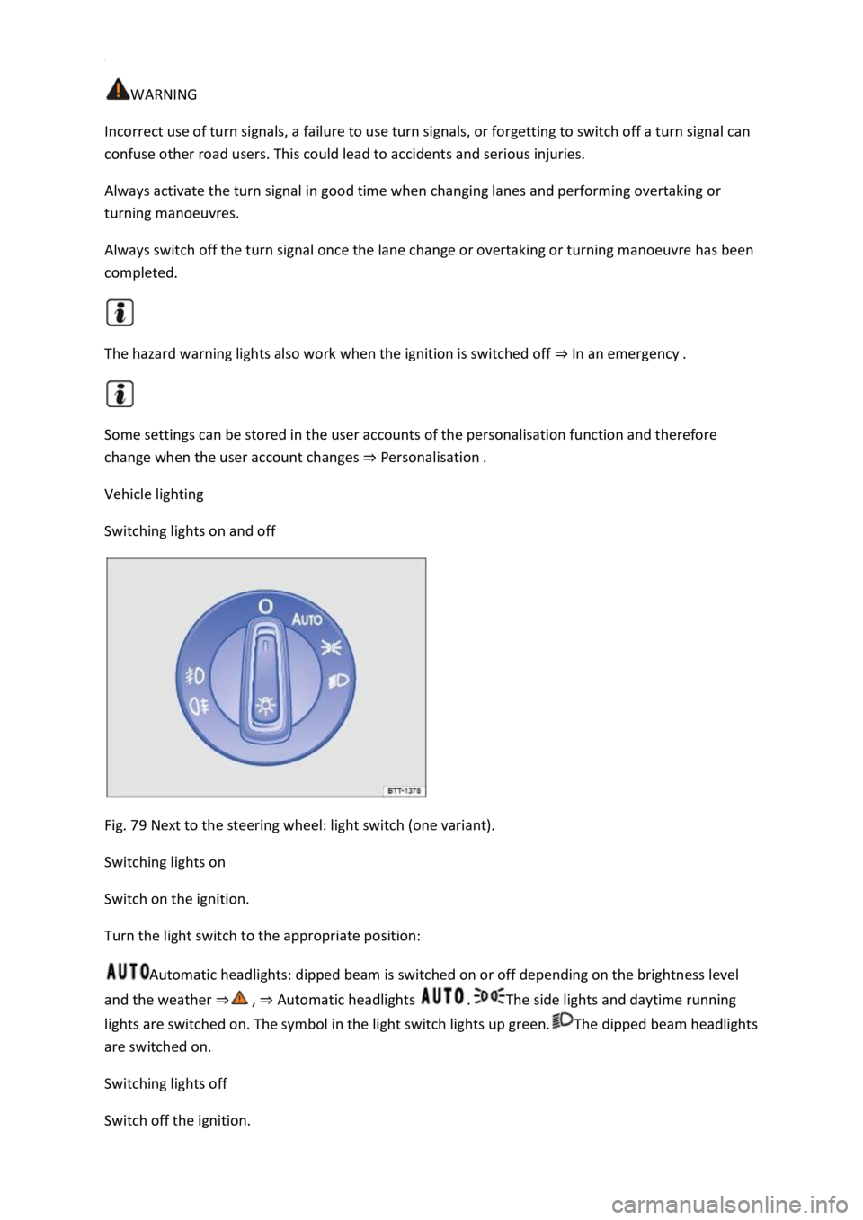
Fig. 79 Next to the steering wheel: light switch (one variant).
Switching lights on
Switch on the ignition.
Turn the light switch to the appropriate position:
Automatic headlights: dipped beam is switched on or off depending on the brightness level
and the weather Automatic headlights The side lights and daytime running
lights are switched on. The symbol in the light switch lights up green.The dipped beam headlights
are switched on.
Switching lights off
Switch off the ignition.
Page 345 of 502

Insert the bulb holder into the headlight and turn it clockwise as far as it will go.
Connect the connector to the bulb holder. The connector must audibly click into place.
Push the headlight from the outside into the openings and insert into the bumper.
Use the screwdriver to tighten the securing screws Fig. 169
Fit the cover in the bumper Fig. 169
Stow the wire hook and screwdriver in the vehicle toolkit.
Changing bulbs in the tail light clusters (LED lights)
First read and observe the introductoryinformation and safety warnings
These lamps use LED technology. The LEDs cannot be replaced by customers. If some LEDs fail, this
may be an indication that more elements are on the point of failure. In this case, have the lights
checked and renewed if necessary at a qualified workshop. Volkswagen recommends using a
Volkswagen dealership for this purpose.
Changing bulbs in the number plate light (LED lights)
First read and observe the introductoryinformation and safety warnings
These lamps use LED technology. The LEDs cannot be replaced by customers. If some LEDs fail, this
may be an indication that more elements are on the point of failure. In this case, have the lights
checked and renewed if necessary at a qualified workshop.
Troubleshooting
First read and observe the introductoryinformation and safety warnings
Fault in vehicle lighting
The indicator lamp lights up yellow.
Fault in vehicle lighting or fault in cornering lights.
Check the vehicle lighting and change the appropriate bulb as required Changing bulbs
bulbs are OK or there is a fault in the dynamic cornering light, go to a qualified workshop.
Changing fuses
Introduction
This chapter contains information on the followingsubjects:
Fuses in the dash panel
Page 346 of 502

Fuses in the engine compartment
Fuse table for fuses in the dash panel
Fuse tables for fuses in the engine compartment
Changing a blown fuse
At the time of publication we are unable to provide an complete overview of the locations of the
fuses for the electrical consumers. This is because the vehicle is under constant development,
because fuses are assigned differently according to the vehicle equipment level and because several
electrical consumers may use a single fuse. You can obtain more information about the fuse
assignment from a Volkswagen dealership.
Several electrical consumers can share a single fuse. Conversely, a single consumer could have more
than one fuse.
Therefore fuses should only be replaced when the cause of the fault has been rectified. If a new fuse
blows shortly after fitting, have the electrical system checked by a qualified workshop.
WARNING
High voltages in the electrical system can cause electric shocks, serious burns and death.
WARNING
Using unsuitable or repaired fuses and bridging an electrical circuit without fuses can cause a fire
and serious injuries.
fuse with the same amp rating (same colour and markings) and size.
NOTICE
electrical consumers off and remove the vehicle key from the ignition before changing a fuse.
pened. Dirt and moisture in the fuse
boxes can damage the electrical system.
Page 347 of 502
There are other fuses in the vehicle in addition to those described in this chapter. These should be
changed only by a qualified workshop.
Fuses in the dash panel
Fig. 170 Dash panel on the driver side: fuse box cover.
Fig. 171 Fuse box cover in the dash panel: right-hand drive vehicle, on the front passenger side.
First read and observe the introductoryinformation and safety warnings
Left-hand drive: opening the fuse box in the dash panel
Fig. 170and pull it forward.
Right-hand drive: opening the fuse box in the dash panel
necessary Fig. 171
Fig. 171
Fig. 171
Page 348 of 502
the holder and push it upwards until it audibly clicks into place. Carefully push the stowage
compartment forwards beyond the resistance of the catches Fig. 171
NOTICE
e the covers of the fuse boxes carefully and install them again properly so as to avoid
damage to the vehicle.
boxes can damage the electrical system.
Fuses in the engine compartment
Fig. 172
First read and observe the introductoryinformation and safety warnings
Opening the fuse box in the engine compartment
et In the engine compartment
Fig. 172
y clicks
into place on both sides.
In some vehicles, there is a pair of plastic pliers Fig. 172
NOTICE
tall them again properly so as to avoid
damage to the vehicle.
Page 349 of 502
Fuse table for fuses in the dash panel
Fig. 173 In the dash panel: fuse assignment.
First read and observe the introductoryinformation and safety warnings
The table shows the fuse locations of the electrical consumers relevant for the driver. The first
column in the table contains the location. The other columns contain the fuse type, the amp rating
and the consumer protected by the fuse.
Depending on the market and specification of your vehicle, the fuse numbers and positions may
differ to those given in the table. If necessary, ask your Volkswagen dealership for the exact fuse
assignment.
Fuse location Fig. 173
F410 amps, MINI
Page 350 of 502
-fitted fuse location as shown in illustration Fig. 173
Fuse tables for fuses in the engine compartment
First read and observe the introductoryinformation and safety warnings
The table shows the fuse locations of the electrical consumers relevant for the driver. The first
column in the table contains the location. The other columns contain the fuse type, the amp rating
and the consumer protected by the fuse.
Depending on the market and specification of your vehicle, the fuse numbers and positions may
differ to those given in the table. If necessary, ask your Volkswagen dealership for the exact fuse
assignment.
F65 amps, ATO