Page 564 of 672

5648-2. Steps to take in an emergency
*: Refer to the separate “Scheduled Maintenance Guide” or “Owner’s Manual
Supplement” for the maintenance interval applicable to your veh icle.
■Conditions that the tire pressure warning system may not functi on
properly
P. 5 0 1
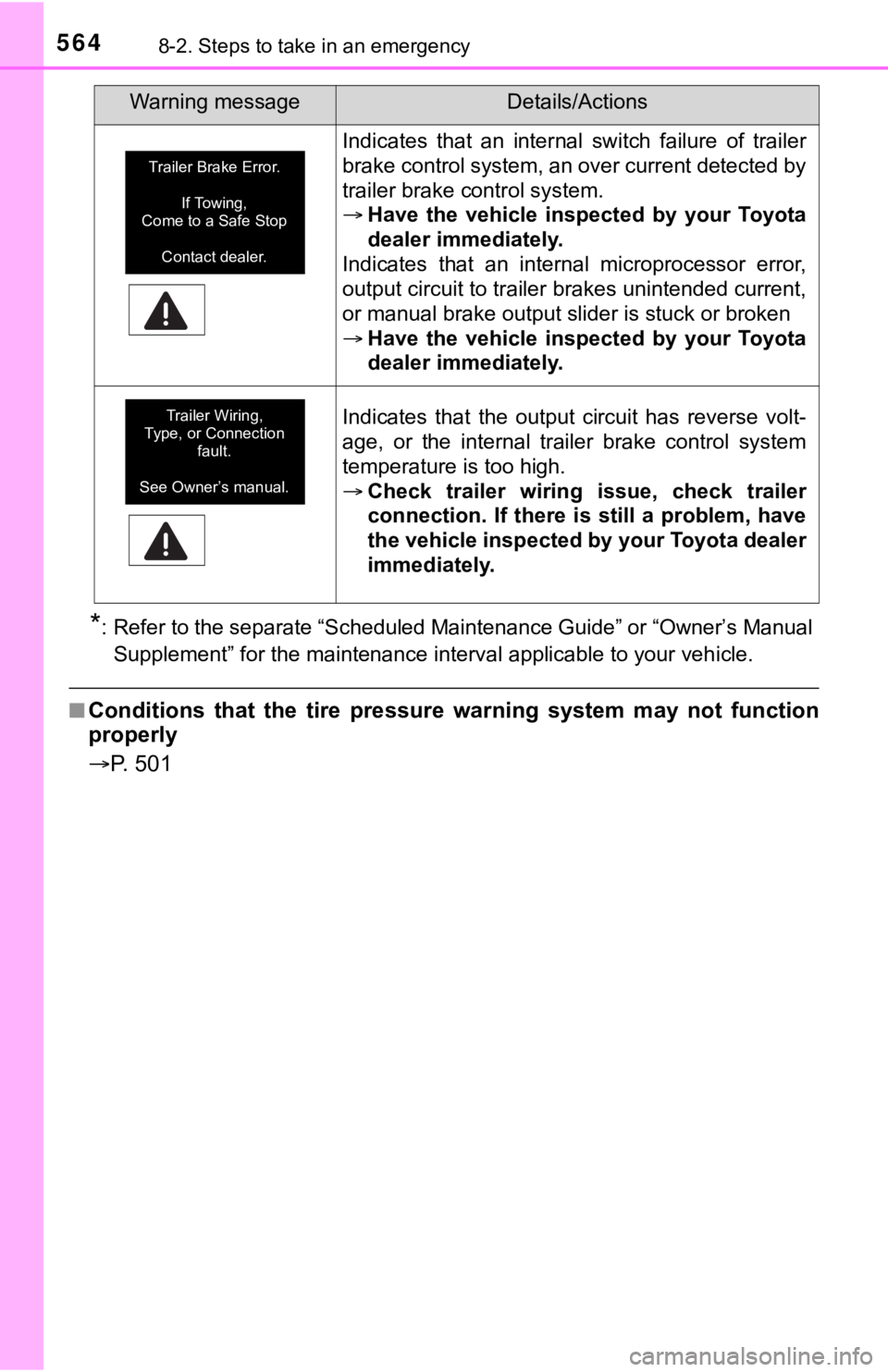
Indicates that an internal switch failure of trailer
brake control system, an over current detected by
trailer brake control system.
Have the vehicle inspected by your Toyota
dealer immediately.
Indicates that an internal microprocessor error,
output circuit to trailer brakes unintended current,
or manual brake output slider is stuck or broken
Have the vehicle inspected by your Toyota
dealer immediately.
Indicates that the output circuit has reverse volt-
age, or the internal trailer brake control system
temperature is too high.
Check trailer wiring issue, check trailer
connection. If there is still a problem, have
the vehicle inspected by your Toyota dealer
immediately.
Warning messageDetails/Actions
Trailer Brake Error.
If Towing,
Come to a Safe Stop
Contact dealer.
Trailer Wiring,
Type, or Connection
fault.
See Owner’s manual.
Page 565 of 672
565
8
When trouble arises
8-2. Steps to take in an emergency
If you have a flat tire
●Stop the vehicle in a safe place on a hard, flat surface.
● Set the parking brake.
● Shift the shift lever to P.
● Stop the engine.
● Turn on the emergency flashers. ( P. 538)
Your vehicle is equipped with a spare tire. The flat tire can b e
replaced with the spare tire.
For details about tires: P. 4 9 5
WARNING
■If you have a flat tire
Do not continue driving with a flat tire.
Driving even a short distance wit h a flat tire can damage the tire and the
wheel beyond repair, which cou ld result in an accident.
Before jacking up the vehicle
Page 573 of 672

5738-2. Steps to take in an emergency
8
When trouble arises
WARNING
■Replacing a flat tire
●Observe the following precautions.
Failure to do so may result in serious injury:
• Lower the spare tire completely to the ground before removing it
from under the vehicle.
• Do not try to remove the wheel ornament by hand. Take due care in
handling the ornament to avoi d unexpected personal injury.
• Do not touch the disc wheels or the area around the brakes imm edi-
ately after the vehicle has been driven.
After the vehicle has been driven the disc wheels and the area
around the brakes will be extreme ly hot. Touching these areas with
hands, feet or other body parts while changing a tire, etc., ma y
result in burns.
●Failure to follow these precautions could cause the wheel nuts to
loosen and the t ire to fall off, resulting in death or serious injury.
• Have the wheel nuts tightened with a torque wrench as soon as pos-
sible after changing wheels.
Steel wheel: 154 ft·lbf (209 N·m, 21.3 kgf·m)
Aluminum wheel: 97 ft·lbf (131 N·m, 13.4 kgf·m)
• When installing a tire, only use wheel nuts that have been spe cifi-
cally designed for that wheel.
• Retighten the wheel nuts within 100 miles (160 km) of driving.
• If there are any cracks or defo rmations in the bolt screws, nut
threads or bolt holes of the wheel, have the vehicle inspected by
your Toyota dealer.
• Do not attach a heavily damaged wheel ornament, as it may fly off
the wheel while the vehicle is moving.
• When installing the wheel nuts, b e sure to install them with the
tapered ends facing inward. ( P. 5 1 1 )
Page 578 of 672

5788-2. Steps to take in an emergency
WARNING
■When using the temporary spare tire
●Remember that the temporary spare tire provided is specifically
designed for use with your vehicle. Do not use your temporary spare
tire on another vehicle.
●Do not use more than one temporary spare tires simultaneously.
●Replace the temporary spare tire with a standard tire as soon a s possi-
ble.
●Avoid sudden acceleration, abrupt steering, sudden braking and shift-
ing operations that cause sudden engine braking.
■When the spare tire is attached
The vehicle speed may not be co rrectly detected, and the following sys-
tems may not operate correctly:
Also, not only can the following system not be utilized fully, but it may
even negatively affect the drive-train components:
• 4WD system
■Speed limit when using th e temporary spare tire
Do not drive at speeds in excess of 50 mph (80 km/h) when a tem porary
spare tire is installed on the vehicle.
The temporary spare tire is not designed for driving at high sp eeds. Fail-
ure to observe this precaution ma y lead to an accident causing death or
serious injury.
• ABS & Brake assist
• VSC
•TRAC
•AUTO LSD
• Pre-Collision System*
*: If equipped • Automatic High Beam*
• LDA (Lane Departure Alert)*
• Dynamic radar cruise control*
• Cruise control*
• Navigation system*
Page 588 of 672

5888-2. Steps to take in an emergency
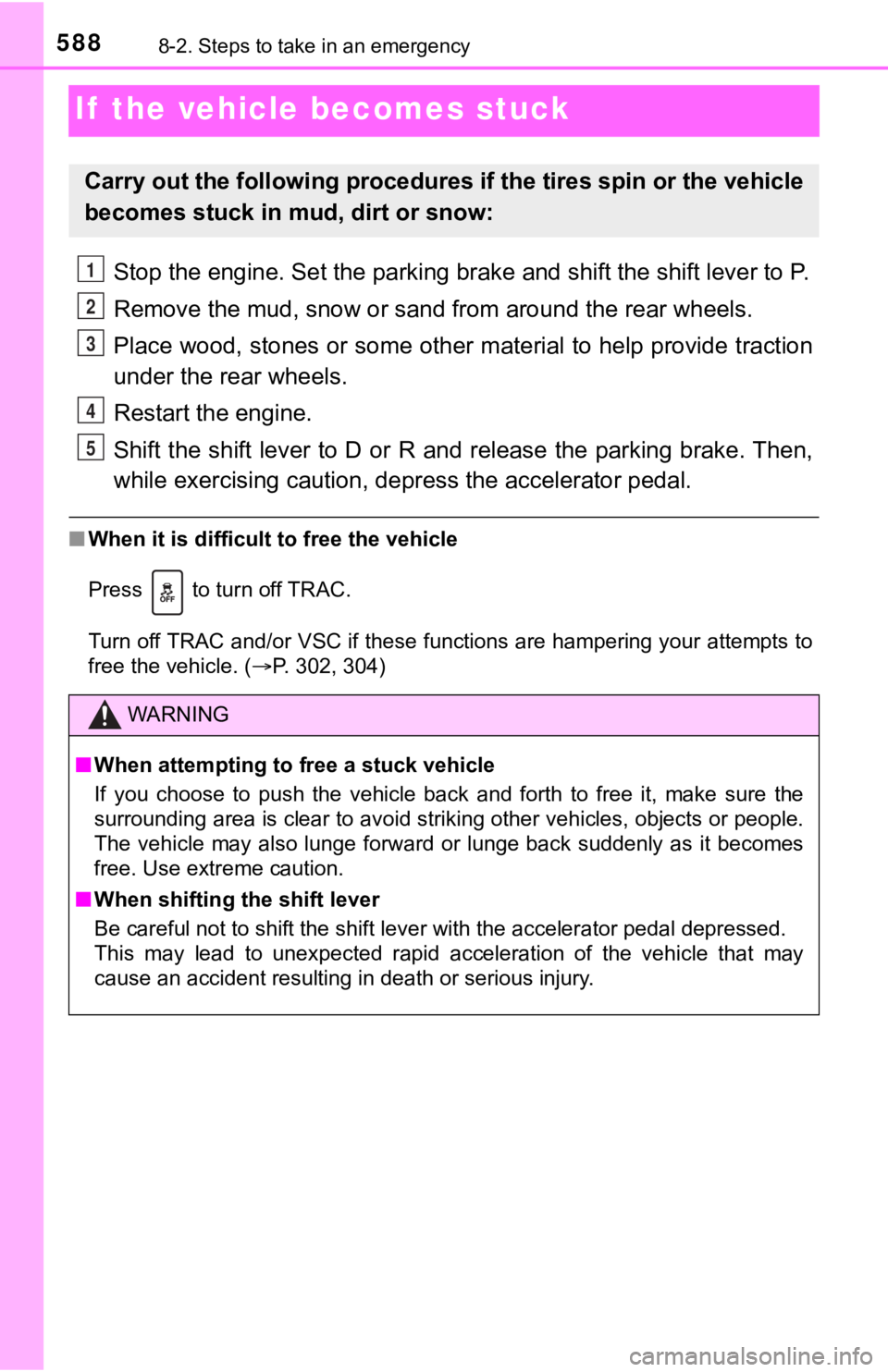
If the vehicle becomes stuck
Stop the engine. Set the parking brake and shift the shift lever to P.
Remove the mud, snow or sand from around the rear wheels.
Place wood, stones or some other material to help provide tract ion
under the rear wheels.
Restart the engine.
Shift the shift lever to D or R and release the parking brake. Then,
while exercising caution, de press the accelerator pedal.
■When it is difficult to free the vehicle
Press to turn off TRAC.
Turn off TRAC and/or VSC if these functions are hampering your attempts to
free the vehicle. ( P. 302, 304)
Carry out the following procedures if the tires spin or the vehicle
becomes stuck in mud, dirt or snow:
WARNING
■When attempting to f ree a stuck vehicle
If you choose to push the vehicle back and forth to free it, ma ke sure the
surrounding area is clear to avoid striking other vehicles, obj ects or people.
The vehicle may also lunge forward or lunge back suddenly as it becomes
free. Use extreme caution.
■ When shifting the shift lever
Be careful not to shift the shift lever with the accelerator pe dal depressed.
This may lead to unexpected rapid acceleration of the vehicle t hat may
cause an accident resulting in death or serious injury.
1
2
3
4
5
Page 607 of 672

6079-1. Specifications
9
Vehicle specifications
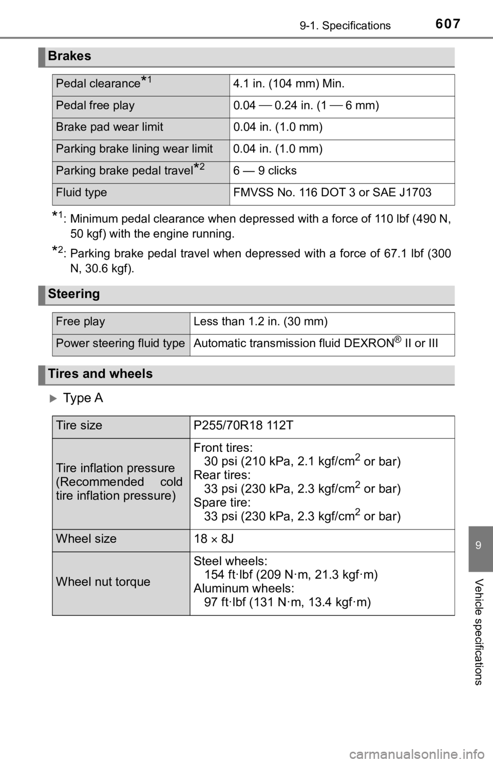
*1: Minimum pedal clearance when depressed with a force of 110 lbf (490 N,
50 kgf) with the engine running.
*2: Parking brake pedal travel when depressed with a force of 67.1 lbf (300 N, 30.6 kgf).
Ty p e A
Brakes
Pedal clearance*14.1 in. (104 mm) Min.
Pedal free play 0.04 0.24 in. (1 6 mm)
Brake pad wear limit 0.04 in. (1.0 mm)
Parking brake lining wear limit 0.04 in. (1.0 mm)
Parking brake pedal travel*26 — 9 clicks
Fluid typeFMVSS No. 116 DOT 3 or SAE J1703
Steering
Free playLess than 1.2 in. (30 mm)
Power steering fluid typeAutomatic transmission fluid DEXRON® II or III
Tires and wheels
Tire sizeP255/70R18 112T
Tire inflation pressure
(Recommended cold
tire inflation pressure)
Front tires:
30 psi (210 kPa, 2.1 kgf/cm2 or bar)
Rear tires: 33 psi (230 kPa, 2.3 kgf/cm
2 or bar)
Spare tire: 33 psi (230 kPa, 2.3 kgf/cm
2 or bar)
Wheel size18 8J
Wheel nut torque
Steel wheels:
154 ft·lbf (209 N·m, 21.3 kgf·m)
Aluminum wheels: 97 ft·lbf (131 N·m, 13.4 kgf·m)
Page 619 of 672

6199-1. Specifications
9
Vehicle specifications
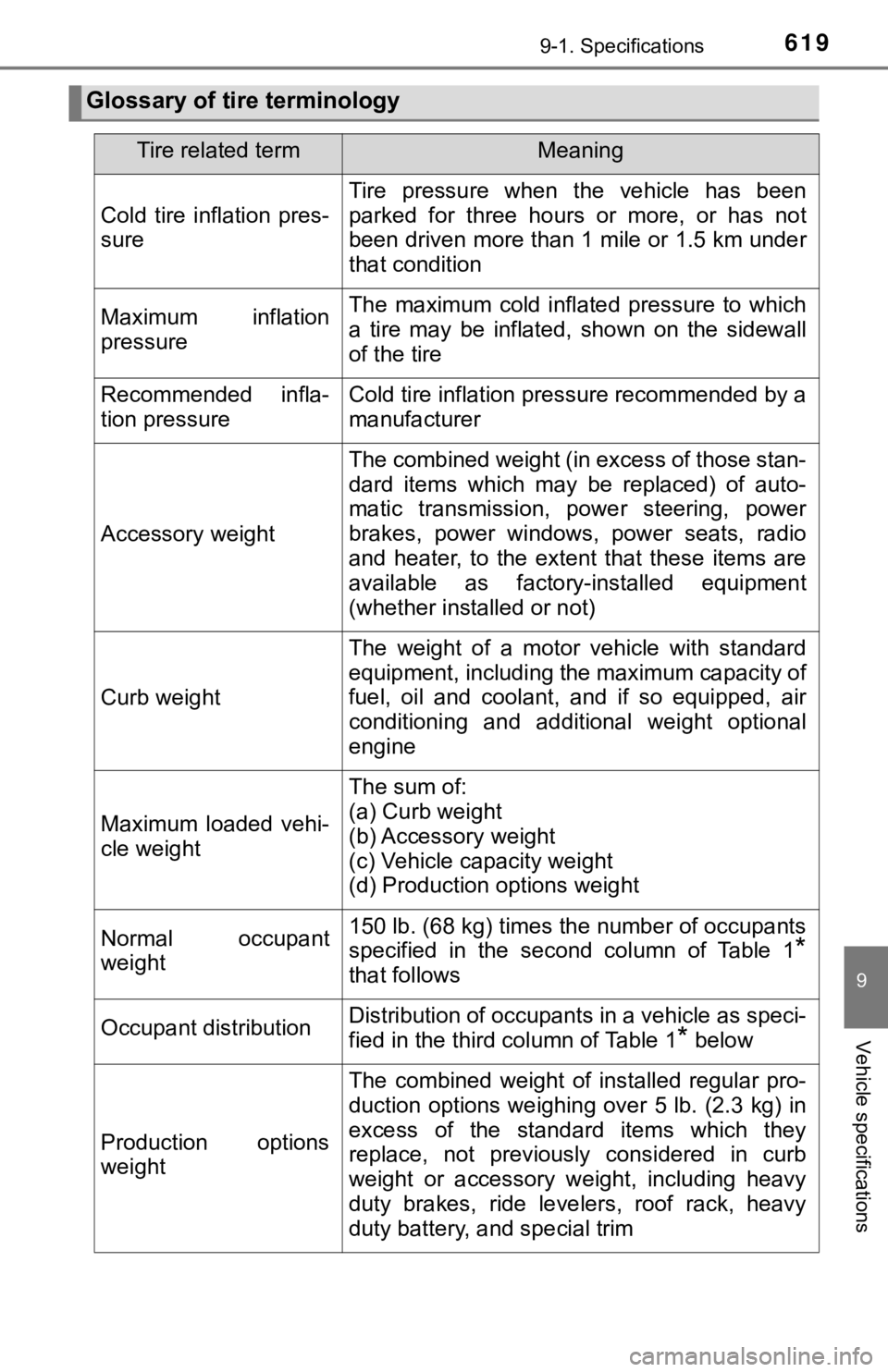
Glossary of tire terminology
Tire related termMeaning
Cold tire inflation pres-
sure
Tire pressure when the vehicle has been
parked for three hours or more, or has not
been driven more than 1 mile or 1.5 km under
that condition
Maximum inflation
pressureThe maximum cold inflated pressure to which
a tire may be inflated, shown on the sidewall
of the tire
Recommended infla-
tion pressureCold tire inflation pressure recommended by a
manufacturer
Accessory weight
The combined weight (in excess of those stan-
dard items which may be replaced) of auto-
matic transmission, power steering, power
brakes, power windows, power seats, radio
and heater, to the extent that these items are
available as factory-installed equipment
(whether installed or not)
Curb weight
The weight of a motor vehicle with standard
equipment, including the maximum capacity of
fuel, oil and coolant, and if so equipped, air
conditioning and additional weight optional
engine
Maximum loaded vehi-
cle weight
The sum of:
(a) Curb weight
(b) Accessory weight
(c) Vehicle capacity weight
(d) Production options weight
Normal occupant
weight150 lb. (68 kg) times the number of occupants
specified in the second column of Table 1
*
that follows
Occupant distributionDistribution of occupants in a vehicle as speci-
fied in the third column of Table 1
* below
Production options
weight
The combined weight of installed regular pro-
duction options weighing over 5 lb. (2.3 kg) in
excess of the standard items which they
replace, not previously considered in curb
weight or accessory weight, including heavy
duty brakes, ride levelers, roof rack, heavy
duty battery, and special trim
Page 628 of 672
6289-2. Customization
■Trailer brake controller* ( P. 308)
*: If equipped
■
Door lock* ( P. 1 1 4 )
*: If equipped
FunctionDefault settingCustomized
setting
TBC trailer type Electric
0-4999lb Electric
5000+ lbO——
E-O-H
0-4999lb
E-O-H
5000+ lb
TBC OFF
123
FunctionDefault settingCustomized setting
Unlocking using a key Driver’s door
unlocked in one step, all doors
unlocked in two
steps All doors
unlocked in one step—— O
Speed-detecting auto-
matic door lock function On Off—O O
Shifting gears to position
other than P locks all
doors Off On
—O O
Shifting gears to P
unlocks all doors
On Off—O O
Opening the driver’s door
unlocks all doors Off On—O O
123