Page 504 of 578

(525,1)
北米Model "A1700BE-B" EDITED: 2017/ 10/ 11
Brake pedalCheck the brake pedal free play and
reserve distance according to the main-
tenance schedule in the“Warranty and
Maintenance Booklet”.&Checking the brake pedal free
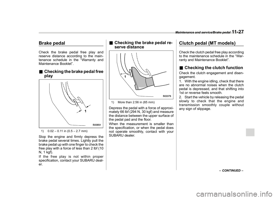
play1) 0.02–0.11 in (0.5–2.7 mm)Stop the engine and firmly depress the
brake pedal several times. Lightly pull the
brake pedal up with one finger to check the
free play with a force of less than 2 lbf (10
N, 1 kgf).
If the free play is not within proper
specification, contact your SUBARU deal-
er.
&Checking the brake pedal re-
serve distance1) More than 2.56 in (65 mm)Depress the pedal with a force of approxi-
mately 66 lbf (294 N, 30 kgf) and measure
the distance between the upper surface of
the pedal pad and the floor.
When the measurement is smaller than
the specification, or when the pedal does
not operate smoothly, contact with your
SUBARU dealer.
Clutch pedal (MT models)Check the clutch pedal free play according
to the maintenance schedule in the“War-
ranty and Maintenance Booklet”.&Checking the clutch functionCheck the clutch engagement and disen-
gagement.
1. With the engine idling, check that there
are no abnormal noises when the clutch
pedal is depressed, and that shifting into
1st or reverse feels smooth.
2. Start the vehicle by releasing the pedal
slowly to check that the engine and
transmission smoothly couple without
any sign of slippage.
–CONTINUED–
Maintenance and service/Brake pedal
11-27
11
Page 505 of 578

(526,1)
北米Model "A1700BE-B" EDITED: 2017/ 10/ 11
&Checking the clutch pedal
free play1) 0.16–0.43 in (4.0–11.0 mm)Lightly depress the clutch pedal down with
your finger until you feel resistance, and
check the free play.
If the free play is not within proper
specification, contact your SUBARU deal-
er.
Hill start assist systemEnsure that the Hill start assist system
operates properly under the following
circumstances.
1. Stop the vehicle on an uphill grade by
depressing the brake pedal (all models)
and clutch pedal (MT models only), with
the engine running.
2. Make sure that the vehicle does not
move backward for several seconds after
the brake pedal is released.
3. Then make sure the vehicle starts
climbing the grade by following the normal
starting procedures.
If the Hill start assist system does not
operate as described above, contact your
SUBARU dealer.
Replacement of brake pad
and liningThe disc brakes have audible wear in-
dicators on the brake pads. If the brake
pads wear close to their service limit, the
wear indicator makes a very audible
scraping noise when the brake pedal is
applied.
If you hear this scraping noise each time
you apply the brake pedal, have the brake
pads serviced by your SUBARU dealer as
soon as possible.
Maintenance and service/Hill start assist system
11-28
Page 523 of 578

(544,1)
北米Model "A1700BE-B" EDITED: 2017/ 10/ 11
the headlight assembly by turning it clock-
wise.
4. Replace the bulb with a new one. At
this time, use care not to touch the bulb
surface.
5. To install the bulb to the headlight
assembly, turn it to the reverse direction
until it clicks.
6. Reconnect the electrical connector.
7.Left-hand side:Set the washer fluid
filler pipe to the original place and secure it
by a clip.
Right-hand side:Install the air intake duct
with clips.&Low beam headlight*, front
side marker light, parking
light* and front turn signal
light**: models without LED headlightsNOTE.If headlight aiming is required, con-
sult your SUBARU dealer for proper
adjustment of the headlight aim.
.It may be difficult to replace the
bulbs. Have the bulbs replaced by your
SUBARU dealer if necessary.
1. Start the engine and turn the steering
wheel fully in the opposite direction of the
bulb to be replaced.2. Stop the engine.
3. Remove the clips from the mud guard.4. Pull off the mud guard.!Low beam headlight
1. Disconnect the electrical connector
from the bulb as pushing the tab.
Maintenance and service/Replacing bulbs
11-46
Page 541 of 578
(564,1)
北米Model "A1700BE-B" EDITED: 2017/ 10/ 11
Fuses and circuits&Fuse panel located in the passenger compartment
Fuse
panelFuse
ratingCircuit
1 20A
R.FOG TRAIL
2 7.5A METER IG
3 15A DOOR LOCK
4 10A
IG2
5 Empty
6 7.5A
MIR
7 15A
UNIT+B
8 7.5A
STOP
9 7.5A
WIPER DEICE
10 7.5A
D-OP+B
11 7.5A
TURN IG
12 15A
UNIT IG1
13 20A
12V PLUG
14 10A
TAIL CLEARANCE
15 10A BKUP+B
16 7.5A
ILM
17 15A
SEAT HTR
18 10A
LAMP IG
19 Empty
20 10A
CIGAR
21 10A
START
22 7.5A
A/C IG
Specifications/Fuses and circuits
12-10