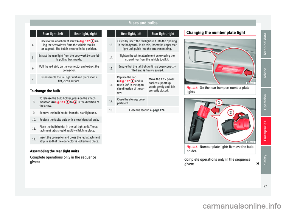
Page 97 of 324

Fuses and bulbs
Replacing the front bumper bulbs Fig. 108
On the right-hand side of the front
b umper: r
emo
ving the headlights. Fig. 109
Changing the bulbs in the head-
lights Complete operations only in the sequence
giv
en:
1.Pull the cover forwards, in the direction of the ar-
row
››› Fig. 108.
2.Unscrew the attachment screw ››› Fig. 108 1 us-
ing the screwdriver from the vehicle tool kit
››› page 83.
3.Tilt the headlight slightly forward and extract it
from its lateral attachments ››› Fig. 109 (small ar-
rows).
4.Release the connector ››› Fig. 109 1 and remove
it.
5.Rotate the bulb holder ››› Fig. 109 2 to the left all
the way, in the direction of the arrow, and pull it
out backwards together with the bulb.
6.Replace the faulty bulb with a new identical bulb.
7.Place the bulb holder in the headlight and rotate
to the right all the way.
8.Insert the connector ››› Fig. 109 1 on the bulb
holder 2. The connector must audibly click into
place.
9.Place the headlight into its position ››› Fig. 109
(small arrows) and tilt it backwards.
10.Tighten the attachment screw ››› Fig. 108 1 us-
ing the screwdriver.
11.Replace the cover on the bumper ››› Fig. 108. Replacing the rear lid bulbs
Fig. 110
On the rear lid: Remove the cover. Fig. 111
On the rear lid: remove the bulb-
ho l
der
. Complete operations only in the sequence
giv
en:
1.Open the rear lid
››› page 124.» 95
Technical data
Advice
Operation
Emergencies
Safety
Page 98 of 324

Emergencies2.Extract the cover carefully using the flat part of the
screwdriver from the vehicle tool kit as a lever
(
››› Fig. 99) on the indent ››› Fig. 110 1
.
3.Release the bulb holder connector by pulling on
the red connector block.
4.Press on the attachment tabs in the direction of
the arrow
››› Fig. 111 and pull out the bulb holder.
5.Replace the faulty bulb with a new identical bulb.
6.Install the bulb holder. The attachment tabs should
audibly click into place.
7.Insert the cover. The cover should lock into place. Replacing the rear bulbs in the body
Fig. 112
On the side of the luggage compart-
ment: r emo
v
ing the left and right hand side
rear lights. 1 remove the cap;
2 attach-
ment s
c
rew Fig. 113
Rear lights in the body: Remove the
b u
l
b holder. 1 to
4 : Attachment tab
Complete operations only in the sequence
giv
en.
R emo
ving the rear light units
Complete operations only in the sequence
given:
Rear light, leftRear light, right
1.Open the rear lid ››› page 124.
2.
Open the storage com-
partments on the left-
hand side of the lug-
gage compartment
››› page 166.Move the 12 V power
socket support by
pressing gently down-
wards ››› Fig. 112 B
(arrow).
3.Rotate the cap 1 90°
in the direction of the
arrow and remove it. 96
Page 99 of 324

Fuses and bulbs Rear light, leftRear light, right
4.Unscrew the attachment screw
››› Fig. 112 2 us-
ing the screwdriver from the vehicle tool kit
››› page 83. The bolt is secured in its position.
5.Extract the rear light from the bodywork by careful-
ly pulling backwards.
6.Pull the red strip on the connector and extract the connector.
7.Disassemble the tail light unit and place it on aflat, clean surface.To change the bulb
8.To release the bulb holder, press on the attach-
ment tabs
››› Fig. 113 1 to 4 in the direction of
the arrow.
9.Remove the bulb holder from the rear light unit.
10.Replace the faulty bulb with a new identical bulb.
11.Place the bulb holder in the tail light unit. The at-
tachment tabs should audibly click into place.
12.Insert the connector and press the red attachment
strip in so that the connector is locked into place. Assembling the rear light units
C
omp
l
ete operations only in the sequence
given:
Rear light, leftRear light, right
13.Carefully insert the tail light unit into the opening in the bodywork. To do this, insert the upper rear light unit guide into the attachment ring.
14.Tighten the white attachment screw using the screwdriver from the vehicle tool kit.
15.Ensure that the tail light unit has been correctly fitted and is firmly secured.
16.
Replace the cap
››› Fig. 112 1 and ro-
tate it 90° in the oppo-
site direction of the ar-
row.Move the 12 V power
socket support up-
wards gently until it is
correctly closed.
17.Close the storage com-
partment.
18.Close the rear lid ››› page 124. Changing the number plate light
Fig. 114
On the rear bumper: number plate
lights Fig. 115
Number plate light: Remove the bulb
ho l
der
. Complete operations only in the sequence
giv
en: »
97
Technical data
Advice
Operation
Emergencies
Safety
Page 100 of 324

Emergencies Fixed number plate
lightBolted number plate light
1.
Press the flat part of the
screwdriver included in
the vehicle on-board
tools (››› Fig. 99) in the
direction of the arrow,
in the groove of the
number plate light
››› Fig. 114.
Unscrew the number
plate light screws using
the screwdriver from
the vehicle tool kit
(››› Fig. 99).
2.Detach the number plate light.
3.
Turn the connector lock
››› Fig. 115 in the direc-
tion of arrow 1
and
pull on the connector.
Separate the attach-
ment tabs from the rear
panel of the number
plate light by pressing.
4.
Rotate the bulb holder
in the direction of the
arrow ››› Fig. 115 2
and extract it together
with the bulb.
Take the bulb holder
out of the number plate
light.
5.Replace the faulty bulb with a new identical bulb.
6.
Insert the bulb holder
into the number plate
light and rotate all the
way in the opposite di-
rection to the arrow
››› Fig. 115 2
.
Insert the bulb holder
into the number plate
light.
7.Plug the connector into
the bulb holder.
Press on the attach-
ment tabs. The bulb
holder must be firmly
attached to the number
plate light.
Fixed number plate
lightBolted number plate light
8.Insert the number plate light carefully into the
opening on the bumper. Ensure that the number plate light is in the correct position.
9.
Insert the number plate
light into the bumper
until it audibly clicks in-
to place.Tighten the attachment
screws for the number
plate light using the
screwdriver.98
Page 101 of 324
Page 102 of 324
Operation
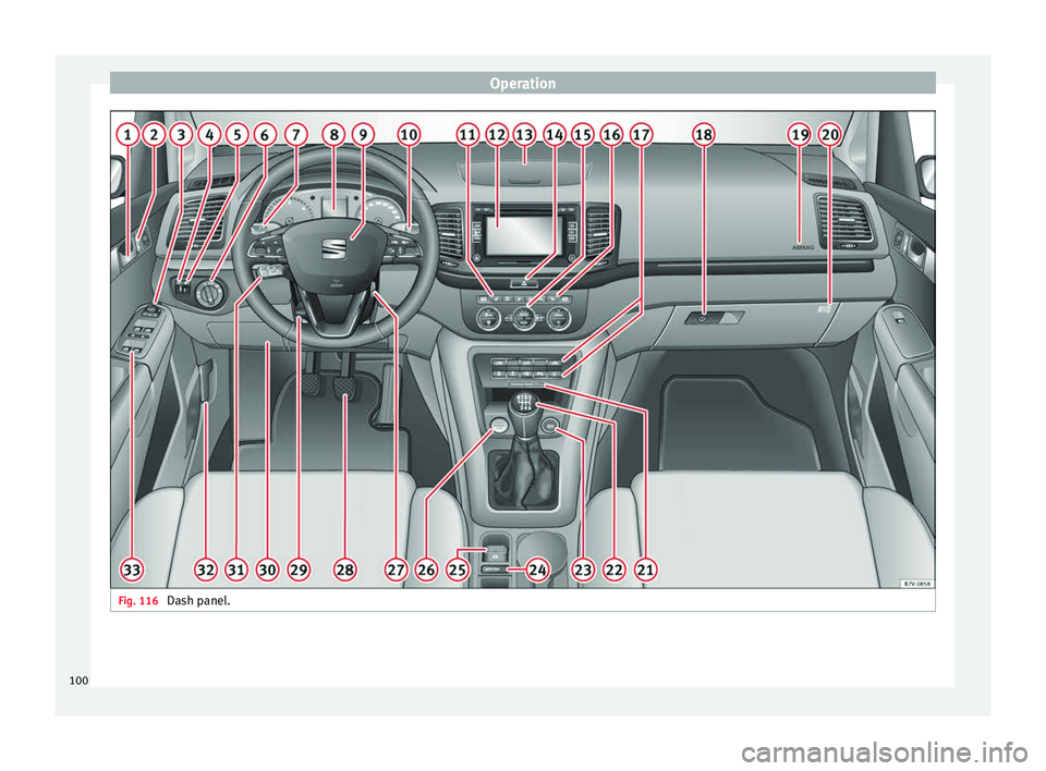
Fig. 116
Dash panel.100
Page 103 of 324

General instrument panel
Operation
Gener a
l
instrument panel
Instrument panel Door release lever
. . . . . . . . . . . . . . . . 121
Central lock button / . . . . . . . . . 114
Switch for adjusting the exterior
mirror s . . . . . . . . . . . . . . . . . . . . . . . . . . . 140
– Exterior mirr or a
djustment
– Exterior mirror heating
– Folding exterior mirrors
Brightness regulation for instru-
ment panel and controls . . . . . . .130
Headlamp range adjustment . . .130
Light switch . . . . . . . . . . . . . . . . . . . 130
– Light off
– Aut
omatic dipped beam head-
light control
– Side/dipped lights /
– Fog lights
Lever for . . . . . . . . . . . . . . . . . . . . . . . . . 130
– Main beam he
adlights
– Headlight flasher
– Turn signals
– Parking lights
Instrument panel:
1 2
3
4
5
6
7
8 –
Ins
truments . . . . . . . . . . . . . . . . . . . . 102
– Digit
al di
splay . . . . . . . . . . . . . . . . . . 102
– Warning and indic
ation lamps . . .107
Steering wheel with horn and – Driver airbag . . . . . . . . . . . . . . . . . . . 19
– On-bo
ard c
omputer controls . . . .27
– Contro
ls for radio, telephone,
navigation and speech dialogue
system ››› Booklet Radio
– Paddle levers for tiptronic gear-
shift (automatic gearbox) . . . . . . .196
Windscreen wiper/ windscreen
wash l
ever . . . . . . . . . . . . . . . . . . . . . . . 137
– Wind s
creen wipers –
– Intermittent wipe
– “Touch wipe” x
– Windscreen wipers
– Automatic windscreen
wash/wipe
– Rear window wiper system
– Automatic rear window
wash/wipe
– Lever with buttons for controlling
the SEAT information system –
/ . . . . . . . . . . . . . . . . . . . . . . . . . 27
Left seat heating controls . . . . . .147
Radio or navigation system (fitted
at fact
ory) ››› Booklet Radio or
››› Booklet Navigation system
9
10
11
12 Storage compartment
. . . . . . . . . . . . .166
Hazard warning lights switch . .134
Switches for: – Electr
onic
manual air condition-
ing . . . . . . . . . . . . . . . . . . . . . . . . . . . . . 176
– Climatr
onic . . . . . . . . . . . . . . . . . . . . . 176
Right seat heating controls . . . . . 147
Button for:
– Anti-slip r
egulation (ASR)
. . . . . . . . . . . . . . . . . . . . . . . . . . . 188
– Star t
-Stop operation . . . . . . . . .208
– Parkin
g distance warning system
(ParkPilot) . . . . . . . . . . . . . . . . . . 211
– Park As
sist system . . . . . . . . . .214
– Tyr
e pressure monitor . . . .234
– Dyn
amic chassis control (DCC)
– Opening the rear lid . . . . . . . . .124
– Opening and clo
sing of electric
sliding doors . . . . . . . . . . . . . . . . 122
Locking handle to open glove com-
par tment . . . . . . . . . . . . . . . . . . . . . . . . . 166
P
osition of passenger front airbag
on the dash p
anel . . . . . . . . . . . . . . . . 19
Key-operated switch in glove com-
partment
for deactivating front pas-
senger front airbag . . . . . . . . . . . . . . .20
Passenger front airbag off warning
lamp . . . . . . . . . . . . . . . . . . . . . . . . . . . . . 73»
13 14
15
16
17
18
19
20
21
101
Technical data
Advice
Operation
Emergencies
Safety
Page 104 of 324

Operation
Lever for:
– Manual
g
earbox . . . . . . . . . . . . . . . . 193
– Automatic
gearbox . . . . . . . . . . . . . 193
12 volt power socket . . . . . . . . . . . . . .173
Auto Hold switch
. . . . . . . . 208
Electronic parking brake switch
. . . . . . . . . . . . . . . . . . . . . . . . . . . . . . . 188
Start-up push button (Keyless Ac-
ces
s closing and start-up system)
Ignition lock . . . . . . . . . . . . . . . . . . . . . . 183
22 23
24
25
26
27 Pedals
. . . . . . . . . . . . . . . . . . . . . . . . . . . 193
Steering column adjustment lev-
er . . . . . . . . . . . . . . . . . . . . . . . . . . . . . . . . 58
Fuse box cover . . . . . . . . . . . . . . . . . . . 91
Lever for: – Crui
se C
ontrol System (CCS) –
– – – – . .221
Open bonnet lever . . . . . . . . . . . . . . . . 271
Controls for: – Electric w
indows . . . . . . . . . . . . 127
28 29
30
31
32
33 –
Chi l
d
proof locks . . . . . . . . . . . . . 121 Note
● Some of the it ems
of equipment listed here
are fitted only on certain model versions or
are optional extras.
● In versions with the steering wheel on the
right, the lay
out of the control elements is
somewhat different. But the symbols as-
signed to the controls correspond to the sym-
bols used in the versions with the steering
wheel on the left Instruments
V iew of
in
strument panel Fig. 117
Instrument panel, on dash panel. Details of the instruments
››
›
Fig. 117: Clock set button1)
.
1 –
Pr e
s
s the button to select the hour
or minute display.
102