Page 296 of 364

5.4
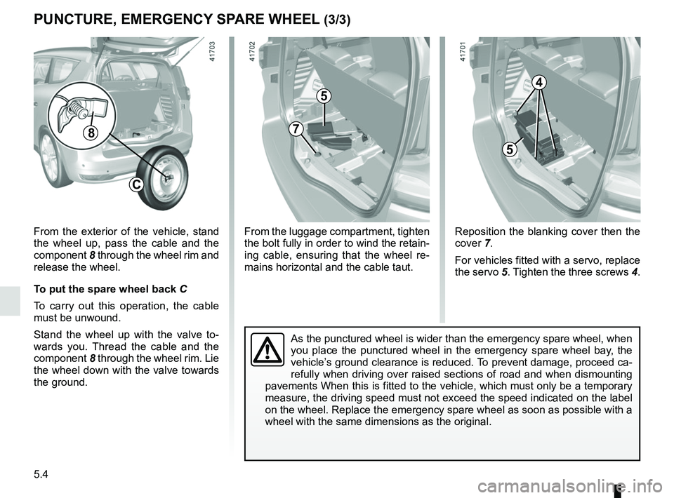
8
C
From the exterior of the vehicle, stand
the wheel up, pass the cable and the
component 8 through the wheel rim and
release the wheel.
To put the spare wheel back C
To carry out this operation, the cable
must be unwound.
Stand the wheel up with the valve to-
wards you. Thread the cable and the
component 8 through the wheel rim. Lie
the wheel down with the valve towards
the ground.
PUNCTURE, EMERGENCY SPARE WHEEL (3/3)
Reposition the blanking cover then the
cover 7.
For vehicles fitted with a servo, replace
the servo 5. Tighten the three screws 4.
5
7
From the luggage compartment, tighten
the bolt fully in order to wind the retain-
ing cable, ensuring that the wheel re-
mains horizontal and the cable taut.
As the punctured wheel is wider than the emergency spare wheel, when
you place the punctured wheel in the emergency spare wheel bay, the
vehicle’s ground clearance is reduced. To prevent damage, proceed ca-
refully when driving over raised sections of road and when dismounting
pavements When this is fitted to the vehicle, which must only be a tempo\
rary
measure, the driving speed must not exceed the speed indicated on the la\
bel
on the wheel. Replace the emergency spare wheel as soon as possible with\
a
wheel with the same dimensions as the original.
4
5
Page 301 of 364

5.9
TOOLS (1/2)
Do not leave the tools un-
secured inside the vehicle
as they may come loose
under braking. After use,
check that all the tools are correctly
clipped into the tool kit, then posi-
tion it correctly in its housing: risk of
injury.
If wheel bolts are supplied in the tool
kit, you must use these bolts, and
only these, for the emergency spare
wheel: refer to the label affixed to
the emergency spare wheel.
The jack is designed for wheel
changing purposes only. Under no
circumstances should it be used for
carrying out repairs underneath the
vehicle or to gain access to the un-
derside of the vehicle.
The presence of the tools depends on
the vehicle.
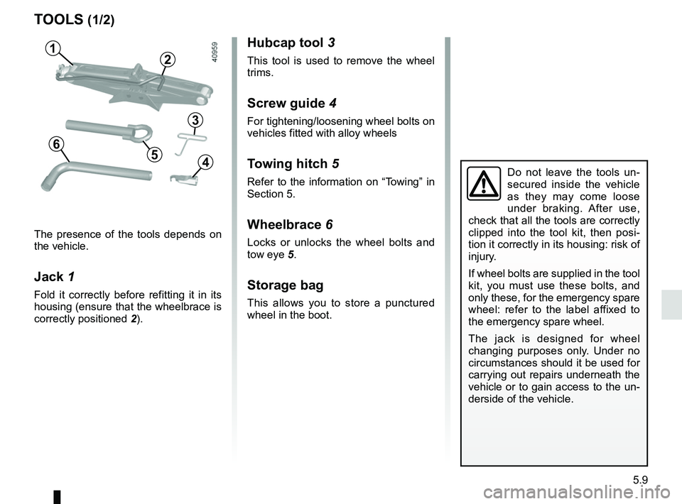
Jack 1
Fold it correctly before refitting it in its
housing (ensure that the wheelbrace is
correctly positioned 2).
Hubcap tool 3
This tool is used to remove the wheel
trims.
Screw guide 4
For tightening/loosening wheel bolts on
vehicles fitted with alloy wheels
Towing hitch 5
Refer to the information on “Towing” in
Section 5.
Wheelbrace 6
Locks or unlocks the wheel bolts and
tow eye 5.
Storage bag
This allows you to store a punctured
wheel in the boot.
1
6
3
5
2
4
Page 302 of 364
5.10
TOOLS (2/2)
5-seater version
Lift the luggage compartment carpet.
The tools are in the bag 7 held in place
by a strap.
7-seater version
Lift the third row rear right-hand seat,
pull back the strap 8 and take out the
bag containing the tools.
To put it back, fold the jack fully, then
store it together with the other tools in
the tool bag. Reposition the bag con-
taining the tools into its housing. Check
that the assembly is correctly posi-
tioned (to avoid noise).
8
7
After use, reposition the bag 7
against the partition and tighten the
strap 8, pulling its free end towards
the vehicle interior.
Page 314 of 364
5.22
Fog light 12
Unscrew the flap located under the
rear bumper using a flat-blade screw-
driver or similar. Access the bulb holder,
then unscrew it by turning towards the
centre of the vehicle.
Bulb type: P21W.
REAR LIGHTS AND SIDE LIGHTS: replacing the bulbs (4/5)
12
LED lighting
The lights are equipped with an LED
lighting system as soon as the side
lights are switched on.
Consult an approved Dealer to replace
the LEDs.
This lighting does not replace a faulty
side light.
13
High level brake light 13
Consult an approved Dealer.
Page 320 of 364
5.28
FUSES (2/2)
Allocation of fuses
(the presence of certain fuses depends on the vehicle equipment level)\
Symbol Allocation SymbolAllocation
HWindscreen washer“Hybrid Assist” system
ëThird row accessories socket, boot accessories
socketÝTowbar socket
ÆFront cigarette lighter, front and rear second row
accessories socketDiagnostic socket, audio alarm
Not usedÌHorn
Heated door mirrorsInstrument panel, dashboard control lighting
×Brake lights, passenger compartment central unitRear electric windows
\bParking brakefFront windscreen wiper
Additional servoDDirection indicator lights, hazard warning lights
îRadio, multifunction screen, multimedia acces-
sories sockets, parking brake controlRear USB sockets on console
Passenger compartment centre unit, rear wiper,
rear fog light
OLocking the doors and luggage compartment
Page 328 of 364

5.36
TOWING: breakdown (1/2)
Before towing, put the gearbox in neu-
tral, unlock the steering column and re-
lease the parking brake.
For vehicles fitted with an automatic
gearbox, if it is not possible to put the
gear lever into position N, please con-
sult an authorised dealer.
Steering column unlocking
Insert the key into the ignition or, de-
pending on the vehicle, with the
RENAULT card on you, press the
engine start button for approximately
2 seconds.
Reposition the lever to neutral (posi-
tion N for vehicles fitted with an auto-
matic gearbox).
The steering column unlocks, the ac-
cessory functions are powered: you
can use the vehicle’s lights (direction
indicators, brake lights, etc.). At night
the vehicle must have its lights on.
Depending on the vehicle, once you
have finished towing, press the engine
start button twice (risk of running down
the battery). The speed specified by current legis-
lation for towing must always be ob-
served. If your vehicle is the towing
vehicle, do not exceed the maximum
towing weight for your vehicle (refer to
the information on “Weights” in
Section 6).
Towing a vehicle with an
automatic gearbox
Transport the vehicle on a trailer or tow
it with the front wheels off the ground.
In exceptional circumstances
, you
may tow it with all four wheels on the
ground, only in a forward gear, with the
gear lever in neutral position N over a
maximum distance of 50 miles (80 km)
and at a maximum speed of 16 mph
(25 km/h).
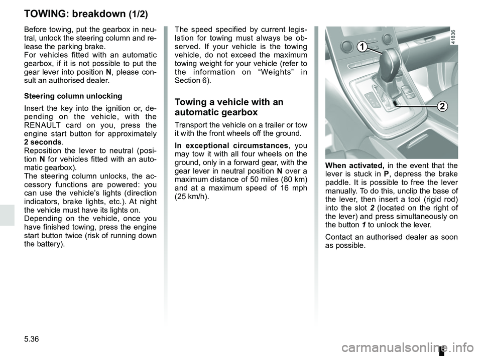
When activated, in the event that the
lever is stuck in P , depress the brake
paddle. It is possible to free the lever
manually. To do this, unclip the base of
the lever, then insert a tool (rigid rod)
into the slot 2 (located on the right of
the lever) and press simultaneously on
the button 1 to unlock the lever.
Contact an authorised dealer as soon
as possible.
2
1
Page 329 of 364

5.37
TOWING : breakdown (2/2)
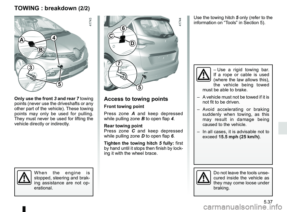
Only use the front 3 and rear 7 towing
points (never use the driveshafts or any
other part of the vehicle). These towing
points may only be used for pulling.
They must never be used for lifting the
vehicle directly or indirectly.Access to towing points
Front towing point
Press zone A and keep depressed
while pulling zone B to open flap 4.
Rear towing point
Press zone C and keep depressed
while pulling zone D to open flap 6.
Tighten the towing hitch 5 fully: first
by hand until it stops then finish by lock-
ing it with the wheel brace.
Do not leave the tools unse-
cured inside the vehicle as
they may come loose under
braking.
Use the towing hitch 5 only (refer to the
information on “Tools” in Section 5).
B
AC
D
– Use a rigid towing bar.
If a rope or cable is used
(where the law allows this),
the vehicle being towed
must be able to brake.
– A vehicle must not be towed if it is not fit to be driven.
– Avoid accelerating or braking suddenly when towing, as this
may result in damage being
caused to the vehicle.
– In all cases, it is advisable not to exceed 15.5 mph (25 km/h).
When the engine is
stopped, steering and brak-
ing assistance are not op-
erational.
37
55
6
4
Page 337 of 364

6.1
Section 6: Technical specifications
Vehicle identification plates . . . . . . . . . . . . . . . . . . . . . . . . . . . . . . . . . . . . \
. . . . . . . . . . . . . . . . . . . . 6.2
Engine identification plates . . . . . . . . . . . . . . . . . . . . . . . . . . . . . . . . . . . .\
. . . . . . . . . . . . . . . . . . . . 6.3
Dimensions . . . . . . . . . . . . . . . . . . . . . . . . . . . . . . . . . . . .\
. . . . . . . . . . . . . . . . . . . . . . . . . . . . . . . . 6.4
Engine specifications . . . . . . . . . . . . . . . . . . . . . . . . . . . . . . . . . . . . \
. . . . . . . . . . . . . . . . . . . . . . . . . 6.6
Weights . . . . . . . . . . . . . . . . . . . . . . . . . . . . . . . . . . . .\
. . . . . . . . . . . . . . . . . . . . . . . . . . . . . . . . . . . 6.7
Towing weights . . . . . . . . . . . . . . . . . . . . . . . . . . . . . . . . . . . .\
. . . . . . . . . . . . . . . . . . . . . . . . . . . . . 6.7
Replacement parts and repairs . . . . . . . . . . . . . . . . . . . . . . . . . . . . . . . . . . . . \
. . . . . . . . . . . . . . . . . 6.8
Service sheets . . . . . . . . . . . . . . . . . . . . . . . . . . . . . . . . . . . . \
. . . . . . . . . . . . . . . . . . . . . . . . . . . . . . 6.9
Anticorrosion check . . . . . . . . . . . . . . . . . . . . . . . . . . . . . . . . . . . . \
. . . . . . . . . . . . . . . . . . . . . . . . . . 6.15