Page 177 of 348

2.65
ADAPTIVE CRUISE CONTROL (5/7)Switching off the function
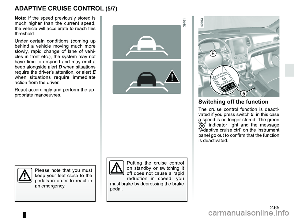
The cruise control function is deacti-
vated if you press switch 5: in this case
a speed is no longer stored. The green
indicator light and the message
"Adaptive cruise ctrl” on the instrument
panel go out to confirm that the function
is deactivated.
Putting the cruise control
on standby or switching it
off does not cause a rapid
reduction in speed: you
must brake by depressing the brake
pedal.
Please note that you must
keep your feet close to the
pedals in order to react in
an emergency.
Note: if the speed previously stored is
much higher than the current speed,
the vehicle will accelerate to reach this
threshold.
Under certain conditions (coming up
behind a vehicle moving much more
slowly, rapid change of lane of vehi-
cles in front etc.), the system may not
have time to respond and may emit a
beep alongside alert D when situations
require the driver’s attention, or alert E
when situations require immediate
action from the driver.
React accordingly and perform the ap-
propriate manoeuvres.
D
5
E
Page 179 of 348

2.67
ADAPTIVE CRUISE CONTROL (7/7)
Limitation of the system operation
– A vehicle travelling in the opposite direction will not trigger any alert\
or any action on the system operation.
– The sensor area should be kept clean and free of any modifications in or\
der to ensure the proper operation of the
system.
– Fixed obstacles (stationary vehicles, traffic jams, toll booths etc.) or objects travelling at low speed or of a \
small size ( motor-
bikes, bicycles, pedestrians etc.) may not be detected by the system.
– A vehicle entering the same lane will only be detected once it has entere\
d the detection zone. Sudden or late braking may then take place.
– When entering a bend or curve, the sensor may temporarily no longer dete\
ct the vehicle in front, and this may lead to acce- leration.
– When exiting a curve, the detection of the vehicle in front may be affected or delayed. Sudden or late braking may then take place.
– A slower vehicle travelling in an adjacent lane may be detected and cause\
a slowing down if one of the two vehicles is trav- elling too close to the lane of the other.
– The system is deactivated below around 20 mph (40 km/h). Drivers must \
react accordingly.
– Sudden changes in situation are not instantly taken into account by the \
system. Drivers must remain vigilant at all times and
under all circumstances.
Deactivating the function
You must disable the function if:
– the brake lights are not functioning;
– the front of the vehicle has undergone an impact or been damaged;
– the vehicle is being towed (breakdowns);
– traffic is heavy;
– the vehicle is travelling in a tunnel;
– the vehicle is travelling on a windy road;
– the vehicle is travelling on a slippery road or in poor weather conditio\
ns (fog, snow, rain, side winds etc.).
In the event of the system behaving abnormally, deactivate it and consult an authorised dealer.
Page 191 of 348
2.79
Operation
With the selection lever 1 in position P,
switch on the ignition.
To move out of position P, you must de-
press the brake pedal before pressing
the unlocking button 2.
With your foot on the brake pedal (warn-
ing light
Ó on the display goes out),
move the lever out of position P.
Only engage D or R when the vehi-
cle is stopped, with your foot on the
brake and the accelerator pedal re-
leased.
Selector lever 1
P: park
R: reverse
N: Neutral
D: automatic mode
M: manual mode
+: upper gear
–: lower gear
The gear engaged is displayed on the
instrument panel B and on the dis-
play A.
Note: Press button 2 to go from posi-
tion D or N to R or P.
AUTOMATIC TRANSMISSION (1/3)
A
Gear shift paddles 3
(depending on the vehicle)
The paddles 3 enable you to change
gear while the gear lever is in “manual
mode” position or, if driving, in “auto-
matic mode” position.
P, N and R are not accessible using the
paddles.
33
1
2
B
Page 248 of 348
3.54
Permissible nose weight, maxi-
mum permissible towing weight,
braked and unbraked: refer to
the information on “Weights” in
Section 6.
Choice and fitting of towing
equipment
Maximum weight of towing equip-
ment:
– 36 kg (5-door version);
– 37 kg (4-seater and estate ver-
sions).
For fitting and conditions of use,
refer to the equipment’s fitting in-
structions.
Please keep these instructions with
the rest of the vehicle documenta-
tion.
TRANSPORTING OBJECTS towbar
A
A: 895 mm (5-door version)
A: 1120 mm (estate version)
A: 1127 mm (4-door version)
If the towbar ball obscures the regis-
tration plate or the rear fog lights, it
should be removed when not in use.
In all cases, comply with local leg-
islation.
Page 261 of 348

4.9
LEVELS (2/3)
Brake fluid level
This should be checked frequently, and
any time you notice even the slightest
loss in braking efficiency.
The level should be read with the engine
switched off and on level ground.Level 2
It is normal for the level to drop as
the linings become worn, but it should
never drop below the “MINI” warning
line.
If you wish to check the disc and drum
wear yourself, you should obtain the
document explaining the checking pro-
cedure from our network or from the
manufacturer’s website. Topping up
After any operation on the hydraulic cir-
cuit, a specialist must replace the fluid.
Only use fluids approved by our
Technical Department (and taken from
a sealed container).
Replacement intervals
Refer to the Maintenance Document for
your vehicle.
Please note when work-
ing close to the engine that
it may be hot. The engine
cooling fan may also start
at any moment. The
warning
light in the engine compartment re-
minds you of this.
Risk of injury.
2
Before performing any
action in the engine com-
partment, the ignition must
be switched off (please see
the information on “Starting, stop-
ping the engine” in Section 2).
If there is an abnormal or repeated
drop in the fluid level, consult an ap-
proved dealer.
Page 277 of 348

5.5
TYRE PRESSURE KIT (2/3)
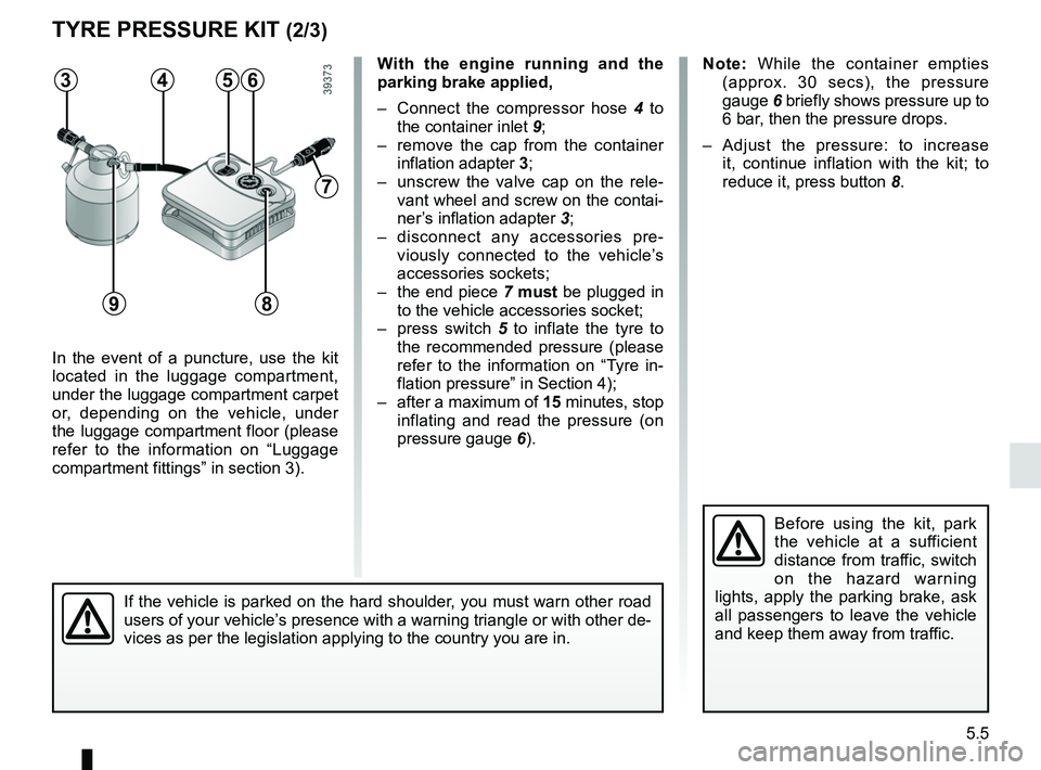
In the event of a puncture, use the kit
located in the luggage compartment,
under the luggage compartment carpet
or, depending on the vehicle, under
the luggage compartment floor (please
refer to the information on “Luggage
compartment fittings” in section 3).
Before using the kit, park
the vehicle at a sufficient
distance from traffic, switch
on the hazard warning
lights, apply the parking brake, ask
all passengers to leave the vehicle
and keep them away from traffic.
Note: While the container empties (approx. 30 secs), the pressure
gauge 6 briefly shows pressure up to
6 bar, then the pressure drops.
– Adjust the pressure: to increase it, continue inflation with the kit; to
reduce it, press button 8.
If the vehicle is parked on the hard shoulder, you must warn other road
users of your vehicle’s presence with a warning triangle or with other de-
vices as per the legislation applying to the country you are in.
With the engine running and the
parking brake applied,
– Connect the compressor hose 4 to
the container inlet 9;
– remove the cap from the container inflation adapter 3;
– unscrew the valve cap on the rele- vant wheel and screw on the contai-
ner’s inflation adapter 3;
– disconnect any accessories pre- viously connected to the vehicle’s
accessories sockets;
– the end piece 7 must be plugged in
to the vehicle accessories socket;
– press switch 5 to inflate the tyre to
the recommended pressure (please
refer to the information on “Tyre in-
flation pressure” in Section 4);
– after a maximum of 15 minutes, stop inflating and read the pressure (on
pressure gauge 6).563
9
7
4
8
Page 281 of 348

5.9
CHANGING A WHEEL (1/2)
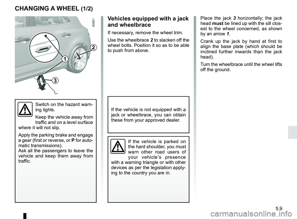
Place the jack 3 horizontally; the jack
head must be lined up with the sill clos-
est to the wheel concerned, as shown
by an arrow 1.
Crank up the jack by hand at first to
align the base plate (which should be
inclined further inwards than the jack
head).
Turn the wheelbrace until the wheel lifts
off the ground.
Switch on the hazard warn-
ing lights.
Keep the vehicle away from
traffic and on a level surface
where it will not slip.
Apply the parking brake and engage
a gear (first or reverse, or P for auto-
matic transmissions).
Ask all the passengers to leave the
vehicle and keep them away from
traffic.
If the vehicle is parked on
the hard shoulder, you must
warn other road users of
your vehicle’s presence
with a warning triangle or with other
devices as per the legislation apply-
ing to the country you are in.
If the vehicle is not equipped with a
jack or wheelbrace, you can obtain
these from your approved dealer.
Vehicles equipped with a jack
and wheelbrace
If necessary, remove the wheel trim.
Use the wheelbrace 2 to slacken off the
wheel bolts. Position it so as to be able
to push from above.
3
2
1
Page 288 of 348
5.16
REAR LIGHTS AND SIDE LIGHTS: replacing the bulbs (1/9)
5-door version
Side light 3
Consult an approved dealer.
2
Access to the bulb holders 6
and 7
Open the boot, remove the cover 4 to
access the screw 5 and undo it.
Remove the rear lights unit.
Direction indicator light 2
Turn bulb holder 7 a quarter of a turn
and take out the bulb.
Bulb type: PY21W.
1
3
Brake light 1
Turn bulb holder 6 a quarter of a turn
and take out the bulb.
Bulb type: P21W.
Refit the bulb holder and push the unit
in fully until it locks in place.
Check that the light is properly locked
in position.
Tighten the screw 5 and reposition the
cover 4.
6
7
4
5