Page 152 of 332

2.48
ACTIVE EMERGENCY BRAKING (10/11)
Active emergency braking
This function is an additional driving aid. This function is not under any circumstances intended to replace the due\
care
and attention of the driver, who should at all times be in control of the vehicle. The triggering of this function may be
delayed or prevented when the system detects clear signs of control of t\
he vehicle by the driver (action on the steer-
ing wheel, pedals etc.).
System servicing/repairs
– In the event of an impact, the radar-camera or radar alignment may be ch\
anged, and its operation may consequently be af- fected. Deactivate the function, then consult an authorised dealer.
– Any work in the area where the radar-camera or radar are located (repai\
rs, replacements, windscreen modifications etc.) must be carried out by a qualified professional.
Only an authorised dealer is qualified to service the system.
In the event of system disturbance
Some conditions can disturb or damage the operation of the system, such \
as:
– a complex environment (metal bridge, tunnel etc.);
– poor weather conditions (snow, hail, black ice etc.);
– poor visibility (night, fog etc.);
– poor contrast between the object (vehicle, pedestrian etc.) and the su\
rrounding area (e.g. pedestrian dressed in white lo- cated in a snowy area etc.);
– being dazzled (glaring sun, lights of vehicles travelling in the opposi\
te direction etc.);
– windscreen obscured (by dirt, ice, snow, condensation etc.).
Risk of inadvertent braking.
Page 153 of 332

2.49
ACTIVE EMERGENCY BRAKING (11/11)
Limitation of the system operation
– A vehicle travelling in the opposite direction will not trigger any alert\
or any action on the system operation.
– The radar-camera area on the windscreen should be kept clean and free of\
any modifications in order to ensure the
proper operation of the system.
– The system cannot respond to small vehicles such as motorbikes or bicycl\
es as effectively as to other vehicles.
– The system may not operate properly when the road surface is slippery (\
rain, snow, black ice etc.).
– To ensure correct operation, System B needs to distinguish the complete outline of the pedestrian. So the sys\
tem cannot
detect:
- Pedestrians in the darkness or in poor lighting conditions;
- Partially visible pedestrians;
- Pedestrians less than approximately 80cm tall;
- Pedestrian carrying large objects;
Deactivating the function
You must disable the function if:
– the brake lights are not functioning;
– the area of the radar-camera has been damaged (on the windscreen side o\
r the interior rear-view mirror side);
– the vehicle is being towed (breakdowns);
– the windscreen is cracked or distorted (do not carry out repairs on thi\
s area of the windscreen; have it changed by an Authorised Dealer).
Halting the function
You can halt the active braking function at any time by tapping the accel\
erator pedal or by turning the steering wheel in a avo id-
ance manoeuvre.
In the event of the system behaving abnormally, deactivate it and consult an authorised dealer.
Page 156 of 332

2.52
2
65
Adjustment
Vehicles fitted with a navigation
system
From the multifunction screen 2, select
“Vehicle”, “Driving assistance”, “Lane
departure warning settings”.
– Volume: adjust the alert volume to one of five levels;
– sensitivity: adjust the sensitivity level for line detection. To do this select:
– “Low” line detected upon cross-
ing;
– “Average” line detected on ap-
proach;
– “high” line detected nearby.
Vehicles not fitted with a navigation
system
– With the vehicle at a standstill, press and hold the switch 5 OK to access
the settings menu;
– repeatedly press the control 6 up or
down until you reach the “Driving as-
sistance” menu. Press the switch 5
OK;
– repeatedly press control 6 up or
down until you reach the “Lane de-
parture warning settings” menu, then
press the switch 5 OK.
– Volume: adjust the alert volume to one of three levels;
– sensitivity: adjust the sensitivity level for line detection. To do this select:
– “Low” line detected upon cross-
ing;
– “Average” line detected on ap-
proach;
– “high” line detected nearby.
Operating faults
In the event of a malfunction, a mes-
sage “Lane departure warning check” is
displayed on the instrument panel, and
the visibility indicators for the left and
right lines disappear from the instru-
ment panel.
Consult an approved dealer.
LANE DEPARTURE WARNING (3/3)
Conditions for non-activation
of alerts
– Direction indicators activated for less than around 2 seconds prior to de-
parting from the lane;
– very fast lane departure;
– driving continuously on a line;
– on bends, the function allows for slightly cutting the bend;
– hazard warning lights activated;
– ...
Page 161 of 332

2.57
1
BLIND SPOT WARNING (3/4)
Operation
This function will indicate:
– when the vehicle speed is between approximately 30 km/h (19 mph) and
140 km/h (87 mph);
– when another vehicle is in the blind spot area and travelling in the same
direction as your vehicle.
If another vehicle is being overtaken,
the indicator 6 will be activated only if
that vehicle remains in the blind spot for
more than one second.
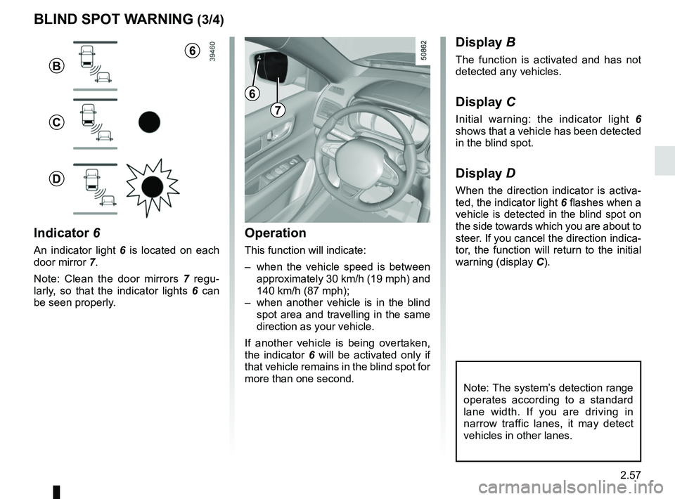
Indicator 6
An indicator light 6 is located on each
door mirror 7.
Note: Clean the door mirrors 7 regu-
larly, so that the indicator lights 6 can
be seen properly.
Display B
The function is activated and has not
detected any vehicles.
Display C
Initial warning: the indicator light 6
shows that a vehicle has been detected
in the blind spot.
Display D
When the direction indicator is activa-
ted, the indicator light 6 flashes when a
vehicle is detected in the blind spot on
the side towards which you are about to
steer. If you cancel the direction indica-
tor, the function will return to the initial
warning (display C).
7
6
B
C
D
Note: The system’s detection range
operates according to a standard
lane width. If you are driving in
narrow traffic lanes, it may detect
vehicles in other lanes.
6
Page 162 of 332

2.58
Operating faults
If the system detects a fault, the mes-
sage “Check blind spot alert” is dis-
played on the instrument panel. Consult
an authorised dealer.
Note: When the engine is started, the
indicator light 6 (display B) flashes
three times. It is normal.
– The system’s detection
range operates according
to a standard lane width. If
you are driving in wide traf-
fic lanes, the system might not
be able to detect a vehicle in the
blind spot.
– The system might be disrupted momentarily if it is exposed to
strong electromagnetic waves
(as beneath high-tension power
lines) or to very poor weather
conditions (heavy rain, snow,
etc.). Remain aware of driving
conditions.
There is a risk of accidents.
BLIND SPOT WARNING (4/4)
Because sensors have
been installed in the bump-
ers, any work (repairs, re-
placements, touching up of
paintwork) must be carried out by a
qualified professional.
6
B
C
D
Conditions for non-function
– If the object is not moving;
– if traffic is heavy;
– the road is winding;
– if front and rear sensors both detect objects at the same time (e.g. when
passing an articulated lorry).
– ...
Page 166 of 332

2.62
SPEED LIMITER FUNCTION (1/3)
Switching on
Press switch 1 on side . The indica-
tor light
comes on, lit orange, and
the message “Speed limiter” appears
on the instrument panel, accompanied
by dashes to indicate that the speed
limiter function is activated and waiting
to store a limited speed.
To store the current speed, press the
switch 2 on side a (+): the limited speed
will replace the dashes.
The minimum stored speed is 20 mph
(30 km/h).
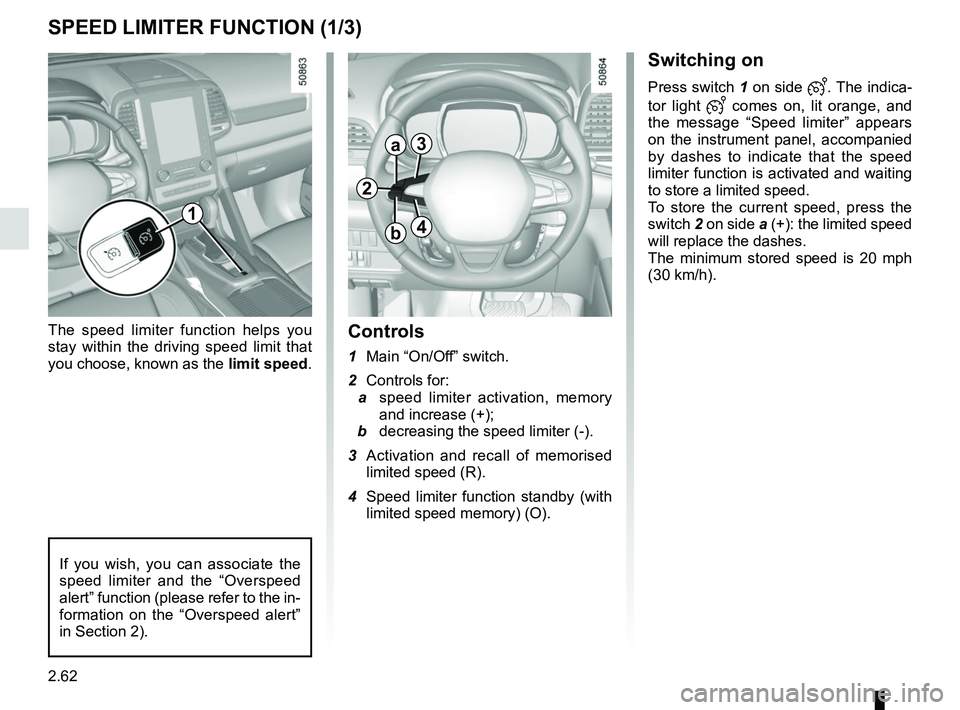
Controls
1 Main “On/Off” switch.
2 Controls for:
a speed limiter activation, memory
and increase (+);
b decreasing the speed limiter (-).
3 Activation and recall of memorised limited speed (R).
4 Speed limiter function standby (with limited speed memory) (O).
The speed limiter function helps you
stay within the driving speed limit that
you choose, known as the
limit speed.
If you wish, you can associate the
speed limiter and the “Overspeed
alert” function (please refer to the in-
formation on the “Overspeed alert”
in Section 2).
1
2
a3
4b
Page 168 of 332
2.64
SPEED LIMITER FUNCTION (3/3)
Recalling the limit speed
If a speed has been saved, it can be re-
called by pressing switch 3 ((R)).
Putting the function on
standby
The speed limiter function is sus-
pended when you press switch 4 (O).
In this case, the speed limit remains
stored and the message “Memorised”
accompanied by this speed appears on
the instrument panel.
Switching off the function
The speed limiter function is deacti-
vated if you press switch 1: in this case
a speed is no longer stored. The orange
warning light and message on the
instrument panel goes out to confirm
that the function is deactivated.
When the speed limiter is put on
standby, pressing side a (+) on
the switch 2 reactivates the func-
tion without taking into account
the stored speed: it is the speed at
which the vehicle is moving that is
taken into account.
2
a3
41
Page 170 of 332

2.66
CRUISE CONTROL FUNCTION (2/4)
Driving
Once a cruising speed is memorised
and the cruise control function is active,
you may lift your foot off the accelera-
tor pedal.
Please note that you are
strongly advised to keep
your feet close to the pedals
in order to react in an emer-
gency.
Activating cruise control
At a steady speed (above approx.
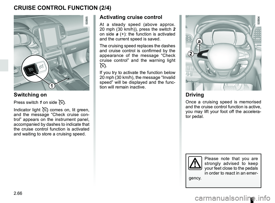
20 mph (30 km/h)), press the switch 2
on side a (+): the function is activated
and the current speed is saved.
The cruising speed replaces the dashes
and cruise control is confirmed by the
appearance of the message “Check
cruise control” and the warning light
.
If you try to activate the function below
20 mph (30 km/h), the message “Invalid
speed” will be displayed and the func-
tion will remain inactive.
Switching on
Press switch 1 on side .
Indicator light
comes on, lit green,
and the message “Check cruise con-
trol” appears on the instrument panel,
accompanied by dashes to indicate that
the cruise control function is activated
and waiting to store a cruising speed.
2
a
1