Page 217 of 264
5.23
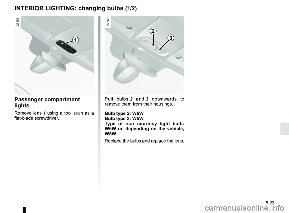
Passenger compartment
lights
Remove lens 1 using a tool such as a
flat-blade screwdriver.
INTERIOR LIGHTING: changing bulbs (1/2)
1
Pull bulbs 2 and 3 downwards to
remove them from their housings.
Bulb type 2: W6W
Bulb type 3: W5W Type of rear courtesy light bulb:
W6W or, depending on the vehicle,
W5W
Replace the bulbs and replace the lens.
2
3
Page 218 of 264
5.24
INTERIOR LIGHTING: changing bulbs (2/2)
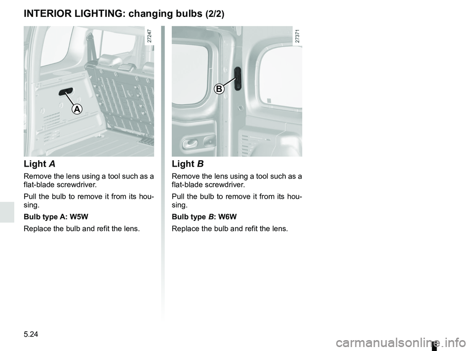
Light A
Remove the lens using a tool such as a
flat-blade screwdriver.
Pull the bulb to remove it from its hou-
sing.
Bulb type A: W5W
Replace the bulb and refit the lens.
Light B
Remove the lens using a tool such as a
flat-blade screwdriver.
Pull the bulb to remove it from its hou-
sing.
Bulb type B: W6W
Replace the bulb and refit the lens.
A
B
Page 219 of 264

5.25
BATTERY: troubleshooting (1/2)
Handle the battery with care
as it contains sulphuric acid,
which must not come into
contact with eyes or skin. If
it does, wash the affected area with
plenty of cold water.
Ensure that naked flames, red hot
objects and sparks do not come into
contact with the battery as there is a
risk of explosion.
To avoid all risk of sparks:
– Ensure that any consumers (cour- tesy lights, etc.) are switched off
before disconnecting or reconnect-
ing the battery.
– When charging, stop the charger before connecting or disconnecting
the battery.
– Do not place metal objects on the battery to avoid creating a short cir-
cuit between the terminals.
– Always wait at least twenty seconds after the engine has been switched
off before disconnecting a battery.
– Make sure that you reconnect the battery terminals after refitting.
Before performing any
action in the engine com-
partment, the ignition must
be switched off (please see
the information on “Starting, stop-
ping the engine” in Section 2).
Connecting a battery charger
The battery charger must be com-
patible with a battery with nominal
voltage of 12 volts.
Switch the engine off and then discon-
nect both battery leads starting with
the negative terminal.
Do not disconnect the battery when the
engine is running. Follow the instruc-
tions given by the manufacturer of
the battery charger you are using.
Please note when work-
ing close to the engine that
it may be hot. In addition,
the engine cooling fan may
start at any moment. The
warning light in the engine compart-
ment reminds you of this.
Risk of injury.
Page 220 of 264

5.26
1
A
2
4
B
3
BATTERY: troubleshooting (2/2)
Connect the positive (+) lead A to (+)
terminal 1 of the discharged battery,
then to (+) terminal 2 of the battery sup-
plying the current.
Connect the negative (–) lead B to (–)
terminal 3 of the battery supplying the
current and then to (–) terminal 4 of the
discharged battery.
Check that there is no contact between
leads A and B and that the positive (+)
lead A is not touching any metal parts
on the vehicle supplying the current.
Start the engine as normal. As soon as
it is running, disconnect leads A and B
in the reverse order (4-3-2-1)
The two batteries must have an iden-
tical nominal voltage of 12 volts.
The
battery supplying the current should
have a capacity (amp-hours, Ah) which
is at least the same as that of the dis-
charged battery.
Ensure that there is no risk of contact
between the two vehicles (risk of short
circuiting when the positive terminals
are connected) and that the discharged
battery is properly connected. Switch
off your vehicle ignition.
Start the engine of the vehicle supply-
ing the current and run it at an interme-
diate engine speed.
Special procedures may be required to charge some batteries. Contact
your approved dealer.
Avoid all risk of sparks which may cause an immediate explosion, and
charge the battery in a well ventilated area.
Risk of serious injury.
1
Starting the vehicle using the
battery from another vehicle
If you have to use the battery from an-
other vehicle to start, obtain suitable
jump leads (with a large cross section)
from an approved dealer or, if you al-
ready have jump leads, ensure that
they are in perfect condition.
Page 221 of 264

5.27
To comply with local legislation, or
as a precaution, you can obtain an
emergency kit containing a set of
spare bulbs and fuses from an ap-
proved Dealer.
FUSES (1/2)
Fuse box
If any electrical component does not
work, check the condition of the fuses.
Unclip cover A. To locate the fuses, please see the fol-
lowing page.
It is not advisable to use the free fuse
locations.
Some functions are protected by fuses
located in the engine compartment.
However, because of their reduced ac-
cessibility,
it is recommended to have
these fuses replaced by an autho-
rised dealer.
Check the fuse in question and replace it, if necessary, with a fuse of
the same rating.
If a fuse is fitted where the rating is too high, it may cause the elect\
rical
circuit to overheat (risk of fire) in the event of an item of equipmen\
t using
an excessive amount of current.
A
1
Tweezers 1
Remove the fuse using tweezers 1, lo-
cated at the back of cover A.
To remove the fuse from the tweezers,
slide the fuse to the side.
Page 222 of 264

5.28
FUSES (2/2)
Number Allocation
1 Fuel pump
2 Not used
3 Passenger compartment
engine cooling fan
4 Passenger compartment
engine cooling fan
5 Rear windscreen wiper
6 Horn, diagnostic socket
7 Heated seats
8 Electric rear windows
9 Passenger compartment
ECU
10 Windscreen washer
11 Brake lights
12 Passenger compartment
unit, ABS, ESP
13 Electric windows, child
safety, heating and air
conditioning system, ECO
mode
14 Not used
15 StarterNumber Allocation
16 Brake lights, additional
equipment, navigation,
ABS, ESP, boot light, tyre
pressure warning light,
interior lights, rain and light
sensor
17 Radio, navigation system,
display, alarm
18 Additional equipment
19 Heated door mirrors
20 Hazard lights, rear fog lights
21 Central locking of opening
elements
22 Instrument panel
23 Rear accessories socket
24 ESC, radio, heating and air
conditioning system, heated
seats, stop lights
25 Front accessories socket
26 Towbar
27 Electric front windows
28 Rear-view mirror control
29 De-icing the rear screen and
rear view mirror
12
3456
78910
11121314
15161718
19202122
23242526
27
28
29
Allocation of fusesThe presence of certain fuses de-
pends on the vehicle equipment
level.
Page 223 of 264

5.29
Replacing windscreen wiper
blades 2
– With the ignition switched off , lift
wiper arm 2 slightly;
– pull tab 1 upwards;
– move the blade in the direction of the arrow.
For refitting, proceed in the reverse
order and ensure that the blade is cor-
rectly clipped on.
WINDSCREEN WIPER BLADES (1/2)
Check the condition of the wiper
blades. You are responsible for their
service life:
– clean the blades, windscreen and rear screen regularly with soapy
water;
– do not use them when the wind- screen or rear screen are dry;
– free them from the windscreen or rear screen when they have not
been used for a long time.
1
Replacing windscreen wiper
blades 3
– With the ignition switched off , lift
wiper arm 5 slightly;
– pull the tab 4 (movement A) and
push the blade upwards.
To refit
Slide the blade along the arm until it
clips on. Make sure that the blade is
correctly locked in position. Return the
windscreen wiper stalk to the park po-
sition.
3
4
5
A
2
Before changing the wiper
blade, make sure the stalk
is in the stop position (deac-
tivated).
Risk of injury.
Page 224 of 264

5.30
WINDSCREEN WIPER BLADES (2/2)
– In frosty weather, make
sure that the wiper blades
are not stuck by ice (to
avoid the risk of the motor
overheating).
– Check the condition of the wiper
blades.
Replace the wiper blades as soon
as they begin to lose efficiency
(approximately once a year).
Whilst changing the blade, take care
not to drop the arm onto the window
after it has been removed as this
may break the window.Replacing the rear screen
wiper blade
Hinged door versions
– With the ignition switched off , lift
wiper arm 8;
– pivot the blade 6;
– press tab 7;
– pull the blade to release it (move- ment B).
For refitting, proceed in the reverse
order and ensure that the blade is cor-
rectly clipped on.
Tailgate versions
– With the ignition switched off , lift
wiper arm 9;
– pivot the blade 10 until some resist-
ance is met;
– pull the blade to release it (move- ment C).
For refitting, proceed in the reverse
order and ensure that the blade is cor-
rectly clipped on.
C
9
10
6
8
7
B