Page 188 of 474
Locking doors
1. Place the ignition switch in the LOCKposition.
2. Close all doors.
3. Press the
Page 196 of 474
Locking doors
1. Place the ignition switch in the LOCKposition.
2. Close all doors.
3. Press the
Page 216 of 474
Entry/Exit function (if so
equipped)
The automatic drive positioner system (if
so equipped) will make the steering wheel
move up automatically when the driver’s
door is opened and the ignition switch is in
the LOCK position. This lets the driver get
into and out of the seat more easily. The
steering wheel moves back into position
when the driver’s door is closed and the
ignition switch is pushed.
For additional information, refer to “Auto-
matic drive positioner” in this section.1. To block glare from the front, swing
down the sun visor
�1.
2. To block glare from the side, remove the sun visor from the center mount
and swing the visor to the side
�2.
3. Slide the sun visor extension
�3in or
out as needed.
Page 219 of 474
For additional information on the compass
display
�3(if so equipped), refer to “Com-
pass display” in the “Instruments and con-
trols” section of this manual.
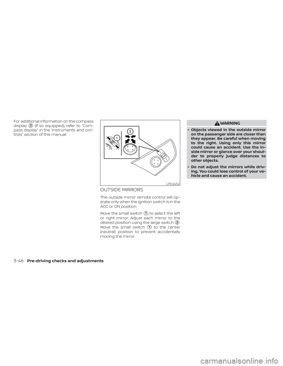
OUTSIDE MIRRORS
The outside mirror remote control will op-
erate only when the ignition switch is in the
ACC or ON position.
Move the small switch
�1to select the lef t
or right mirror. Adjust each mirror to the
desired position using the large switch
�2.
Move the small switch
�1to the center
(neutral) position to prevent accidentally
moving the mirror.
Page 240 of 474
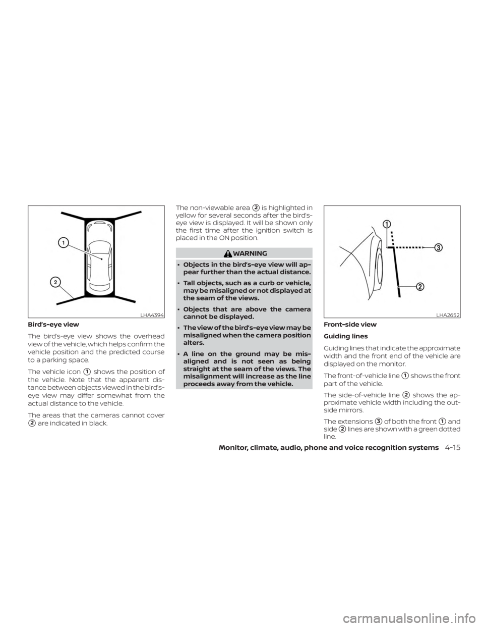
Bird’s-eye view
The bird’s-eye view shows the overhead
view of the vehicle, which helps confirm the
vehicle position and the predicted course
to a parking space.
The vehicle icon
�1shows the position of
the vehicle. Note that the apparent dis-
tance between objects viewed in the bird’s-
eye view may differ somewhat from the
actual distance to the vehicle.
The areas that the cameras cannot cover
�2are indicated in black. The non-viewable area
�2is highlighted in
yellow for several seconds af ter the bird’s-
eye view is displayed. It will be shown only
the first time af ter the ignition switch is
placed in the ON position.
Page 250 of 474

∙ When the ignition switch is placed in the“OFF” position and turned back to the
“ON” position again. To prevent the so-
nar system from activating altogether,
use the “Camera” menu. For additional
information, refer to “Sonar function
settings” in this section.
Sonar function settings
To set up the sonar function to your pre-
ferred settings, press the SETTING button,
select the “Camera/Sonar” key and then
select the “Sonar” key on the center display.
Designs and items displayed on the
screen may vary depending on the mod-
els.
Sonar Volume: Adjust the volume of the
buzzer.
Sonar: When this item is turned ON, the
rear sonar is activated. When this item is
turned OFF (indicator turns off ), the rear
sonar is deactivated. The amber markers
are displayed at the corners of the vehicle
icon. The next time the ignition switch is
placed in the ON position, “sonar is OFF” is
displayed briefly.
Towing mode (if so equipped): When this
item is turned ON, only the rear sonar is
OFF. The amber markers are displayed at
the rear corners of the vehicle icon. Show Camera when Sonar Activate (if so
equipped):
When this item is turned ON,
the camera view is automatically shown on
the display in the case that the distance to
the objects measured by the sonar is be-
coming short.
Sonar Sensitivity: Adjust the sensitivity
level of the sonar higher (right) or lower
(lef t).SONAR SYSTEM LIMITATIONS
Page 273 of 474

Additional information:∙ When replacing a wheel without the TPMS such as the spare tire, the TPMS
does not monitor the tire pressure of
the spare tire.
∙ The TPMS will activate only when the vehicle is driven at speeds above
16 mph (25 km/h). Also, this system may
not detect a sudden drop in tire pres-
sure (for example, a flat tire while driv-
ing).
∙ The low tire pressure warning light does not automatically turn off when the tire
pressure is adjusted. Af ter the tire is in-
flated to the recommended pressure,
the vehicle must be driven at speeds
above 16 mph (25 km/h) to activate the
TPMS and turn off the low tire pressure
warning light. Use a tire pressure gauge
to check the tire pressure.
∙ The “Tire Pressure Low - Add Air” warn- ing appears in the vehicle information
display when the low tire pressure
warning light is illuminated and low tire
pressure is detected. The “Tire Pressure
Low - Add Air” warning turns off when
the low tire pressure warning light turns
off. ∙ The “Tire Pressure Low - Add Air” warn-
ing appears each time the ignition
switch is placed in the on position as
long as the low tire pressure warning
light remains illuminated.
∙ The “Tire Pressure Low - Add Air” warn- ing does not appear if the low tire pres-
sure warning light illuminates to indi-
cate a TPMS malfunction.
∙ Tire pressure rises and falls depending on the heat caused by the vehicle’s op-
eration and the outside temperature.
Do not reduce the tire pressure af ter
driving because the tire pressure rises
af ter driving. Low outside temperature
can lower the temperature of the air
inside the tire which can cause a lower
tire inflation pressure. This may cause
the low tire pressure warning light to
illuminate. If the warning light illumi-
nates, check the tire pressure for all four
tires.
∙ The Tire and Loading Information label is located in the driver’s door opening. ∙ You can also check the pressure of all
tires (except the spare tire) on the ve-
hicle information display screen. The or-
der of the tire pressure figures dis-
played on the screen corresponds with
the actual order of the tire position.
For additional information, refer to “Low tire
pressure warning light” in the “Instruments
and controls” section and “Tire Pressure
Monitoring System (TPMS)” in the “In case of
emergency” section of this manual.
Page 282 of 474

If the Intelligent Key is within the operating
range, it is possible for anyone, even some-
one who does not carry the Intelligent Key,
to push the ignition switch to start the en-
gine.
The operating range of the engine start
function is inside of the vehicle
�1.
∙ The luggage area is not included in the operating range, but the Intelligent Key
may function.
∙ If the Intelligent Key is placed on the instrument panel, inside the glove box,
storage bin or door pocket, the Intelli-
gent Key may not function.
∙ If the Intelligent Key is placed near the door or window outside the vehicle, the
Intelligent Key may function.
PUSH-BUTTON IGNITION SWITCH
POSITIONS
LOCK (Normal parking position)
The ignition switch can only be locked in
this position.
The ignition switch will be unlocked when it
is pushed to the ACC position while carry-
ing the Intelligent Key. The ignition switch will lock when any door
is opened or closed with the ignition
switched off.
ACC (Accessories)
This position activates electrical accesso-
ries, such as the radio, when the engine is
not running.
ACC has a battery saver feature that will
place the ignition switch in the OFF position
af ter a period of time under the following
conditions:
∙ All doors are closed.
∙ The shif t lever is in P (Park).
The battery saver feature will be canceled if
any of the following occur: ∙ Any door is opened.
∙ The shif t lever is moved out of P (Park).
∙ The ignition switch changes position.
ON (Normal operating position)
This position turns on the ignition system
and electrical accessories. ON has a battery saver feature that will
place the ignition switch in the OFF posi-
tion, if the vehicle is not running, af ter some
time under the following conditions:
∙ All doors are closed.
∙ The shif t lever is in P (Park).
The battery saver feature will be canceled if
any of the following occur: ∙ Any door is opened.
∙ The shif t lever is moved out of the P (Park) position.
∙ The ignition switch changes position.


The automatic drive positioner system (if
so equipped) will make the steering wheel
move up automatically when the driver’s
door is opened and the ignition switc")