Page 12 of 426
1. Engine hood (P. 3-13)
2. Wiper and washer switch (P. 2-29)
3. Windshield (P. 8-20)
4. Power windows (P. 2-50)
5. Door locks (P. 3-3)Key fob (P. 3-9)
Keys (P. 3-2)
6. Mirrors (P. 3-17)
7. Tire pressure (P. 8-32) Flat tire (P. 6-2)
Tire chains (P. 8-32)
8. Headlight and turn signal switch
(P. 2-31)
Daytime Running Lights (DRL)
system (P. 2-31)
Replacing bulbs (P. 8-28)
9. Fog light switch (if so equipped)
(P. 2-34)
Refer to the page number indicated in
parentheses for operating details.
LIC3702
EXTERIOR FRONT
Illustrated table of contents0-3
Page 13 of 426
1. Rear window and outside mirror(if so equipped) defroster switch
(P. 2-30)
2. Trailer hitch/towing (P. 10-18)
3. Rearview monitor (P. 4-11)
4. Replacing bulbs (P. 8-28)
5. Fuel-filler cap (P. 3-13) Fuel recommendation (P. 10-2)
Fuel-filler door (P. 3-13)
6. Vehicle loading (P. 10-14)
Refer to the page number indicated in
parentheses for operating details.
LIC3774
EXTERIOR REAR
0-4Illustrated table of contents
Page 14 of 426
1. Map lights (P. 2-51)
2. Sun visors (P. 3-17)
3. Inside mirror (P. 3-17)
4. Steering wheel (P. 3-16)
5. Glove box (P. 2-42)
6. Console box (if so equipped)(P. 2-42)
7. Cup holders (mounted to lower
seat frame) (2nd row shown; 3rd
and 4th rows similar) (P. 2-42)
8. Rear seat configurations (P. 1-2)
Refer to the page number indicated in
parentheses for operating details.
LII2528
PASSENGER COMPARTMENT
Illustrated table of contents0-5
Page 16 of 426
17. Rear Sonar System (RSS)OFF switch (if so equipped) (P. 2-37)
Front and rear sonar system
OFF switch (if so equipped) (P. 2-37)
Power inverter switch
(if so equipped) (P. 2-36)
Heated seat switch
(if so equipped) (P. 2-34)
Tow mode switch (if so equipped)
(P. 2-38)
USB connection port (P. 4-60)
AUX IN jack (P. 4-60)
18. 12v power outlet (P. 2-39)
19. Ignition switch (P. 5-8)
20. Tilt steering wheel control (P. 3-16)
21. Hood release switch (P. 3-13)
22. Fuse box (P. 8-22)
23. Outside power mirror switch
(P. 3-17)
Vehicle Dynamic Control (VDC)
OFF switch (P. 2-35)
*: Refer to the separate NissanConnect®
Owner’s Manual (if so equipped).
Refer to the page number indicated in
parentheses for operating details.
Illustrated table of contents0-7
Page 89 of 426

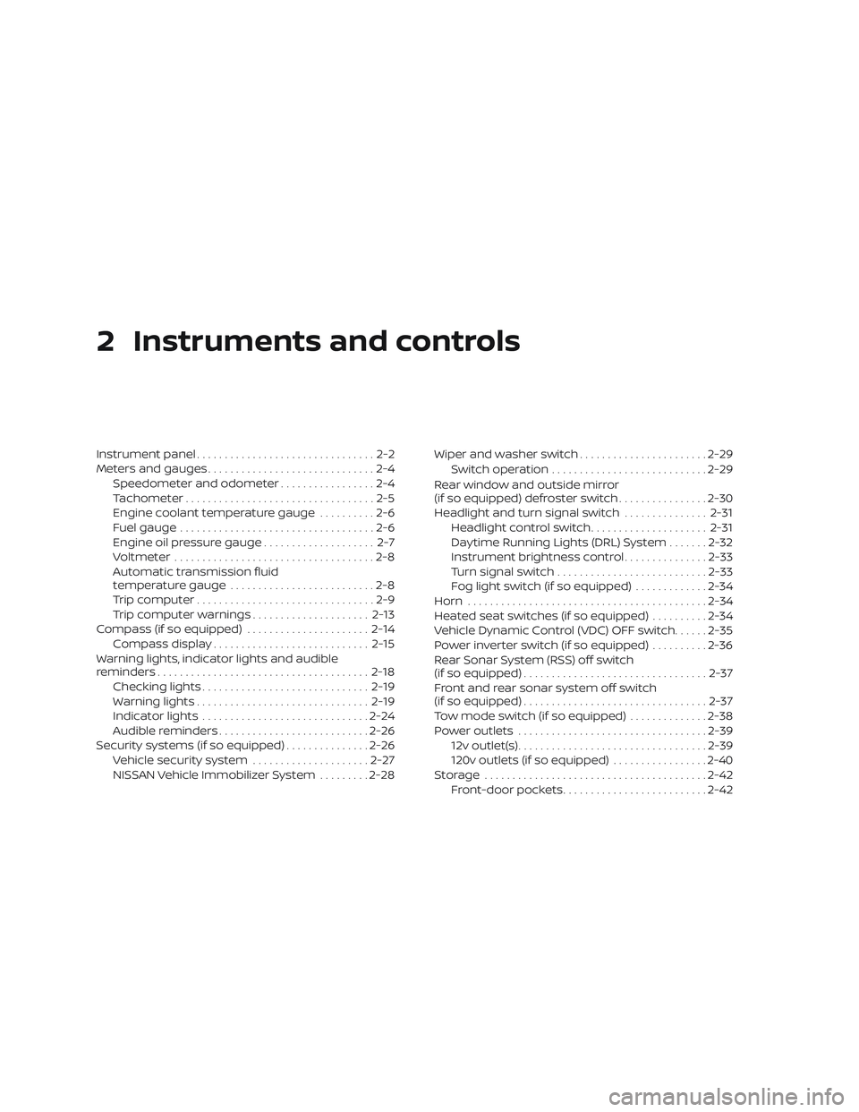
2 Instruments and controls
Instrument panel................................2-2
Meters and gauges ..............................2-4
Speedometer and odometer .................2-4
Tachometer ..................................2-5
Engine coolant temperature gauge ..........2-6
Fuel gauge ...................................2-6
Engine oil pressure gauge .................... 2-7
Voltmeter ....................................2-8
Automatic transmission fluid
temperature gauge ..........................2-8
Trip computer ................................2-9
Trip computer warnings .....................2-13
Compass (if so equipped) ......................2-14
Compass display ............................ 2-15
Warning lights, indicator lights and audible
reminders ...................................... 2-18
Checking lights .............................. 2-19
Warning lights ............................... 2-19
Indicator lights .............................. 2-24
Audible reminders ........................... 2-26
Security systems (if so equipped) ...............2-26
Vehicle security system .....................2-27
NISSAN Vehicle Immobilizer System .........2-28 Wiper and washer switch
.......................2-29
Switch operation ............................ 2-29
Rear window and outside mirror
(if so equipped) defroster switch ................2-30
Headlight and turn signal switch ...............2-31
Headlight control switch .....................2-31
Daytime Running Lights (DRL) System .......2-32
Instrument brightness control ...............2-33
Turn signal switch ........................... 2-33
Fog light switch (if so equipped) .............2-34
Horn ........................................... 2-34
Heated seat switches (if so equipped) ..........2-34
Vehicle Dynamic Control (VDC) OFF switch ......2-35
Power inverter switch (if so equipped) ..........2-36
Rear Sonar System (RSS) off switch
(if so equipped) ................................. 2-37
Front and rear sonar system off switch
(if so equipped) ................................. 2-37
T
ow mode switch (if so equipped) ..............2-38
Power outlets .................................. 2-39
12v outlet(s) .................................. 2-39
120v outlets (if so equipped) .................2-40
Storage ........................................ 2-42
Front-door pockets .......................... 2-42
Page 92 of 426
17. Rear Sonar System (RSS)OFF switch (if so equipped) (P. 2-37)
Front and rear sonar system
OFF switch (if so equipped) (P. 2-37)
Power inverter switch (if so
equipped) (P. 2-36)
Heated seat switch
(if so equipped) (P. 2-34)
Tow mode switch (if so equipped)
(P. 2-38)
USB connection port (P. 4-60)
AUX IN jack (P. 4-60)
18. 12v power outlet (P. 2-39)
19. Ignition switch (P. 5-8)
20. Tilt steering wheel control (P. 3-16)
21. Hood release switch (P. 3-13)
22. Fuse box (P. 8-22)
23. Outside power mirror switch
(P. 3-17)
Vehicle Dynamic Control (VDC)
OFF switch (P. 2-35)
*: Refer to the separate NissanConnect®
Owner’s Manual (if so equipped).
Refer to the page number indicated in
parentheses for operating details.
Instruments and controls2-3
Page 103 of 426

It is recommended that you visit a NISSAN
dealer for this service.
LOW OIL P warning
This warning appears in the message area
of the trip computer if low oil pressure is
detected. This gauge is not designed to
indicate low oil level.The low oil pressure
warning is not designed to indicate a low
oil level. Use the dipstick to check the oil
level. For additional information, refer to
“Engine oil” in the “Do-it-yourself ” section of
this manual.
LO VOLTAGE warning
This warning appears in the message area
of the trip computer if the system detects
that the charging system is not functioning
properly. Have the system checked. It is
recommended that you visit a NISSAN
dealer for this service. For additional infor-
mation, refer to “Voltmeter” in this section.
LOOSE FUEL CAP warning
This warning appears in the message area
of the trip computer when the fuel-filler cap
is not tightened correctly af ter the vehicle
has been refueled. For additional informa-
tion, refer to “Fuel-filler cap” in the “Pre-
driving checks and adjustments” section of
this manual.
A/T TEMP warning
This light comes on when the automatic
transmission oil temperature is too high. If
the message displays in the message area
of the trip computer during normal driving,
pull off the road in a safe area, stop the
engine immediately and have the system
checked. It is recommended that you visit a
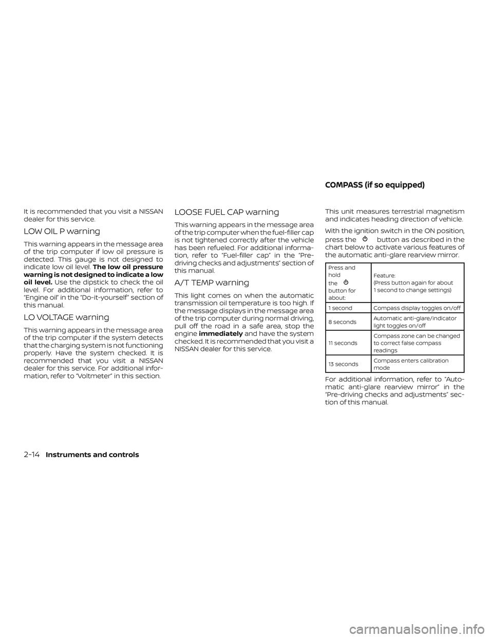
NISSAN dealer for this service. This unit measures terrestrial magnetism
and indicates heading direction of vehicle.
With the ignition switch in the ON position,
press the
button as described in the
chart below to activate various features of
the automatic anti-glare rearview mirror.
Press and
hold
the
button for
about: Feature:
(Press button again for about
1 second to change settings)
1 second Compass display toggles on/off
8 seconds Automatic anti-glare/indicator
light toggles on/off
11 seconds Compass zone can be changed
to correct false compass
readings
13 seconds Compass enters calibration
mode
For additional information, refer to “Auto-
matic anti-glare rearview mirror” in the
“Pre-driving checks and adjustments” sec-
tion of this manual.
COMPASS (if so equipped)
2-14Instruments and controls
Page 106 of 426
Inaccurate compass direction
The compass display is equipped with au-
tomatic correction function. If the correct
direction is not shown, follow this proce-
dure.1. With the display turned on, press and hold the
button for about 13 sec-
onds. The “C” icon in the compass dis-
play will illuminate.
2. Calibrate the compass by driving the vehicle in three complete circles at a
maximum speed of 5 mph (8 km/h).
3. Af ter completing the circles, the display should return to normal.
CAUTION
∙ Do not install a ski rack, antenna, etc.,which are attached to the vehicle by
means of a magnet. They affect the
operation of the compass.
∙ When cleaning the mirror, use a paper towel or similar material dampened
with glass cleaner. Do not spray glass
cleaner directly on the mirror as it
may cause the liquid cleaner to enter
the mirror housing.
Instruments and controls2-17