Page 301 of 426
A. Tire stoppers
B. Flat Tire
Blocking wheels
Place tire stoppers, supplied in tool kit, at
both the front and back of the wheel diago-
nally opposite the flat tire to prevent the
vehicle from moving when it is jacked up.
WARNING
Be sure to block the wheel as the vehicle
may move and result in personal injury.
Getting the spare tire and tools
The jack and tool kit are located behind the
rear passenger side access cover. To re-
move the jack and tool kit perform the fol-
lowing:1. Remove the access cover
�1. 2. To easily access removing the jack, first
remove the tool kit by unscrewing the
retainer
�2counterclockwise.
3. Remove the tool bag.
LCE2142LCE2032LCE2030
6-4In case of emergency
Page 302 of 426

4. To release the jack, lower the jack byturning the jack lever
�3counterclock-
wise until the lock rod
�4canbelow-
ered.
5. Lif t the jack to remove. 6. Assemble the extension and the
J-shaped end tool together before in-
serting them into the oval-shaped
opening above the middle of the rear
step bumper. Pass the J-shaped end of
the jack rod through the opening and
direct it toward the spare tire winch,
located directly above the spare tire.
CAUTION
Do not insert the jack rod straight as it is
designed to be inserted at an angle as
shown. 7. Fit the square end of the jack rod into
the square hole of the wheel nut
wrench to form a handle.
8. Seat the J-shaped end of the jack rod into the opening of the tire winch. Apply
pressure to keep the jack rod engaged
in the spare tire winch and turn the jack
rod counterclockwise to lower the
spare tire.
9. Once the spare tire is completely low- ered, reach under the vehicle, remove
the retainer chain, and carefully slide
the tire from under the rear of the ve-
hicle. Do not remove the rubber spacer.
LCE2031LCE2033LCE2034
In case of emergency6-5
Page 303 of 426
10. To reinstall the wheel, insert the tirechain through the wheel. Be sure the
rubber spacer is centered on the wheel
before lif ting. Use the assembled jack
rod and slowly rotate the winch clock-
wise to raise the wheel to the vehicle.
NOTE:
Inspect the spacer every six years and
replace as necessary. Contact a NISSAN
dealer for replacement parts if neces-
sary.
CAUTION
∙ Be sure to center the spare tire sus- pending plate on the wheel and then
lif t the spare tire.
∙ Failure to use the spacer may allow the chain to get stuck on the wheel
nut holes.
Removing bolt-on wheel caps
CAUTION
Do not use your hands to pry off wheel
caps or wheel covers. Doing so could
result in personal injury.
The wheel cap�1is only attached with the
wheel nuts and is separate from the wheel
�2.
To remove the wheel cap, remove the
wheel nuts af ter the jack is securely sup-
porting the vehicle and the tire clears the
ground.
LCE2017LCE2367
6-6In case of emergency
Page 306 of 426

5. Remove the wheel nuts and thenremove the tire.
Installing the spare tire
The spare tire is designed for emergency
use. For additional information, refer to
“Wheels and tires” in the “Do-it-yourself ”
section of this manual.
1. Clean any mud or dirt from the surface between the wheel and hub.
2. Carefully put the spare tire on and tighten the wheel nuts finger tight.
3. With the wheel nut wrench, tighten wheel nuts alternately and evenly in the
sequence illustrated (
�1,�2,�3,�4,�5,
�6,�7,�8) until they are tight . 4. Lower the vehicle slowly until the tire
touches the ground. Then, with the
wheel nut wrench, tighten the wheel
nuts securely in the sequence illus-
trated (
�1,�2,�3,�4,�5,�6,�7,�8).
Lower the vehicle completely.
WARNING
∙ Incorrect wheel nuts or improperly tightened wheel nuts can cause the
wheel to become loose or come off.
This could cause an accident.
∙ Do not use oil or grease on the wheel studs or nuts. This could cause the
nuts to become loose.
∙ Retighten the wheel nuts when the vehicle has been driven for 600 miles
(1,000 km) (also in cases of a flat tire,
etc.).
As soon as possible, tighten the wheel
nuts to the specified torque with a
torque wrench.
Wheel nut tightening torque:
131 f t-lb (177 N·m)
LCE2012
In case of emergency6-9
Page 307 of 426

The wheel nuts must be kept tightened
to specification at all times. It is recom-
mended that wheel nuts be tightened to
specifications at each lubrication inter-
val.
Adjust tire pressure to the COLD pres-
sure.
COLD pressure: Af ter vehicle has been
parked for 3 hours or more or driven less
than 1 mile (1.6 km).
COLD tire pressures are shown on the
Tire and Loading Information label af-
fixed to the driver side center pillar.
Af ter adjusting tire pressure to the COLD
tire pressure, the display (if so equipped)
of the tire pressure information may
show higher pressure than the COLD tire
pressure af ter the vehicle has been
driven more than 1 mile (1.6 km). This is
because the tire pressure increases as
the tire temperature rises. This does not
indicate a system malfunction.5. Securely store the flat tire and jacking equipment in the vehicle.WARNING
∙ Always make sure that the spare tireand jacking equipment are properly
secured af ter use. Such items can be-
come dangerous projectiles in an ac-
cident or sudden stop.
∙ The spare tire is designed for emer- gency use. For additional information,
refer to “Wheels and tires” in the “Do-
it-yourself ” section of this manual. To start your engine with a booster, the
instructions and precautions below must
be followed.
WARNING
∙ If done incorrectly, jump starting can
lead to a battery explosion, resulting
in severe injury or death. It could also
damage your vehicle.
∙ Explosive hydrogen gas is always present in the vicinity of the battery.
Keep all sparks and flames away from
the battery.
∙ Do not allow battery fluid to come into contact with eyes, skin, clothing or
painted surfaces. Battery fluid is a
corrosive sulfuric acid solution which
can cause severe burns. If the fluid
should come into contact with any-
thing, immediately flush the con-
tacted area with water.
∙ Keep battery out of the reach of children.
∙ The booster battery must be rated at 12 volts. Use of an improperly rated
battery can damage your vehicle.
JUMP STARTING
6-10In case of emergency
Page 353 of 426

WARNING
Radio waves could adversely af")
If you have a flat tire, refer to “Flat tire” in
the “In case of emergency ” section of
this manual.
TIRE PRESSURE
Tire Pressure Monitoring System
(TPMS)
WARNING
Radio waves could adversely affect
electric medical equipment. Those who
use a pacemaker should contact the
electric medical equipment manufac-
turer for the possible influences before
use.
This vehicle is equipped with the Tire Pres-
sure Monitoring System (TPMS). It monitors
tire pressure of all four tires except the
spare. When the low tire pressure warning
light is lit, and the TIRE PRES warning ap-
pears in the trip computer, one or more of
your tires is significantly under-inflated.
The TPMS will activate only when the ve-
hicle is driven at speeds above 16 mph
(25 km/h). Also, this system may not detect
a sudden drop in tire pressure (for example
a flat tire while driving). For additional information, refer to “Low tire
pressure warning light” in the “Instruments
and controls” section, “Tire Pressure Moni-
toring System (TPMS)” in the “Starting and
driving” section and “Flat tire” in the “In case
of emergency” section of this manual.
Tire inflation pressure
Check the tire pressures (including
the spare) of ten and always prior to
long distance trips. The recom-
mended tire pressure specifications
are shown on the F.M.V.S.S./C.M.V.S.S.
certification label or the Tire and
Loading Information label under the
“Cold Tire Pressure” heading. The Tire
and Loading Information label is af-
fixed to the driver side center pillar.
Tire pressures should be checked
regularly because:
∙ Most tires naturally lose air over time.
∙ Tires can lose air suddenly when driven over potholes or other ob-
jects or if the vehicle strikes a
curb while parking.
Rear combination lightLDI2029
WHEELS AND TIRES
8-32Do-it-yourself
Page 355 of 426
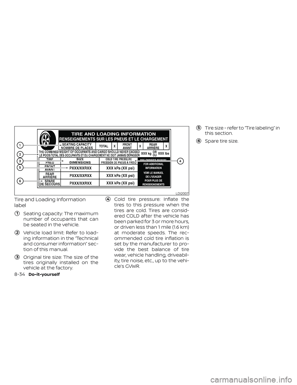
Tire and Loading Information
label
�1Seating capacity: The maximum
number of occupants that can
be seated in the vehicle.
�2Vehicle load limit: Refer to load-
ing information in the “Technical
and consumer information” sec-
tion of this manual.
�3Original tire size: The size of the
tires originally installed on the
vehicle at the factory.
�4Cold tire pressure: Inflate the
tires to this pressure when the
tires are cold. Tires are consid-
ered COLD af ter the vehicle has
been parked for 3 or more hours,
or driven less than 1 mile (1.6 km)
at moderate speeds. The rec-
ommended cold tire inflation is
set by the manufacturer to pro-
vide the best balance of tire
wear, vehicle handling, driveabil-
ity, tire noise, etc., up to the vehi-
cle’s GVWR.
�5Tire size - refer to “Tire labeling” in
this section.
�6Spare tire size.
LDI2007
8-34Do-it-yourself
Page 356 of 426
Checking tire pressure
1. Remove the valve stem cap fromthe tire.
2. Press the pressure gauge squarely onto the valve stem. Do
not press too hard or force the
valve stem sideways, or air will
escape. If the hissing sound of air
escaping from the tire is heard
while checking the pressure, re-
position the gauge to eliminate
this leakage. 3. Remove the gauge.
4. Read the tire pressure on the
gauge stem and compare to the
specification shown on the Tire
and Loading Information label.
5. Add air to the tire as needed. If too much air is added, press the
core of the valve stem briefly
with the tip of the gauge stem to
release pressure. Recheck the
pressure and add or release air
as needed.
6. Install the valve stem cap. 7. Check the pressure of all other
tires, including the spare.
Size Cold Tire
Inflation
Pressure
Front
Original Tire:
LT245/70R17 350kPa, 50 PSI
Rear
Original Tire:
LT245/70R17 550 kPa, 80 PSI
Spare Tire:
LT245/70R17 550 kPa, 80 PSI
LDI0393
Do-it-yourself8-35