Page 104 of 426
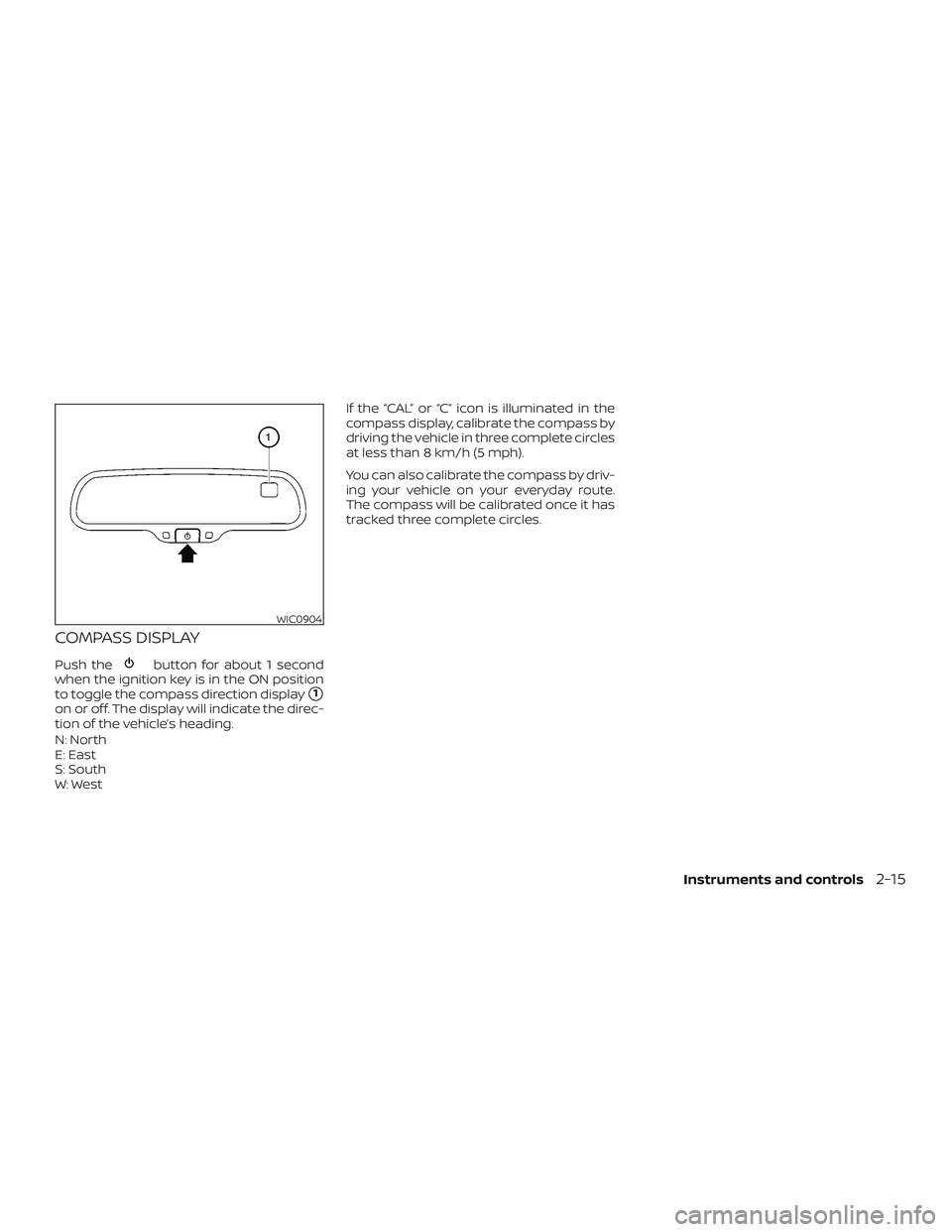
COMPASS DISPLAY
Push thebutton for about 1 second
when the ignition key is in the ON position
to toggle the compass direction display
�1
on or off. The display will indicate the direc-
tion of the vehicle’s heading.
N: North
E: East
S: South
W: West If the “CAL” or “C” icon is illuminated in the
compass display, calibrate the compass by
driving the vehicle in three complete circles
at less than 8 km/h (5 mph).
You can also calibrate the compass by driv-
ing your vehicle on your everyday route.
The compass will be calibrated once it has
tracked three complete circles.
WIC0904
Instruments and controls2-15
Page 105 of 426
Zone variation change procedure
The difference between magnetic north
and geographical north is known as vari-
ance. In some areas, this difference can
sometimes be great enough to cause false
compass readings. Follow these instruc-
tions to set the variance for your particular
location if this happens:1. Press and hold the
button for
about 11 seconds. The current zone
number will appear in the display. Re-
lease the button.
2. Find your current location on the zone map. Refer to the illustration.
3. Press the
button repeatedly to
toggle through the zone numbers until
the desired number appears in the dis-
play. Once you have selected a zone
number, the display will show a com-
pass direction within a few seconds.
WIC0355
2-16Instruments and controls
Page 106 of 426
Inaccurate compass direction
The compass display is equipped with au-
tomatic correction function. If the correct
direction is not shown, follow this proce-
dure.1. With the display turned on, press and hold the
button for about 13 sec-
onds. The “C” icon in the compass dis-
play will illuminate.
2. Calibrate the compass by driving the vehicle in three complete circles at a
maximum speed of 5 mph (8 km/h).
3. Af ter completing the circles, the display should return to normal.
CAUTION
∙ Do not install a ski rack, antenna, etc.,which are attached to the vehicle by
means of a magnet. They affect the
operation of the compass.
∙ When cleaning the mirror, use a paper towel or similar material dampened
with glass cleaner. Do not spray glass
cleaner directly on the mirror as it
may cause the liquid cleaner to enter
the mirror housing.
Instruments and controls2-17
Page 157 of 426

FUEL-FILLER CAP
WARNING
∙ Gasoline is extremely flammable andhighly explosive under certain condi-
tions. You could be burned or seri-
ously injured if it is misused or mis-
handled. Always stop the engine and
do not smoke or allow open flames or
sparks near the vehicle when
refueling. ∙ Do not attempt to top off the fuel tank
af ter the fuel pump nozzle shuts off
automatically. Continued refueling
may cause fuel overflow, resulting in
fuel spray and possibly a fire.
∙ Use only an original equipment type fuel-filler cap as a replacement. It has
a built-in safety valve needed for
proper operation of the fuel system
and emission control system. An in-
correct cap can result in a serious mal-
function and possible injury. It could
also cause the
Malfunction Indi-
cator Light (MIL) to come on.
∙ Never pour fuel into the throttle body to attempt to start your vehicle.
∙ Do not fill a portable fuel container in the vehicle or trailer. Static electricity
can cause an explosion of flammable
liquid, vapor or gas in any vehicle or
trailer. To reduce the risk of serious
injury or death when filling portable
fuel containers:
– Always place the container on the ground when filling.
– Do not use electronic devices when filling. – Keep the pump nozzle in contact
with the container while you are
filling it.
– Use only approved portable fuel containers for flammable liquid.
CAUTION
∙ Do not use E-15 or E-85 fuel in yourvehicle. For additional information,
refer to “Fuel recommendation” in the
“Technical and consumer informa-
tion” section of this manual.
∙ The LOOSE FUEL CAP warning will ap- pear if the fuel-filler cap is not prop-
erly tightened. It may take a few driv-
ing trips for the message to be
displayed. Failure to tighten the fuel-
filler cap properly af ter the LOOSE
FUEL CAP warning appears may cause
the
Malfunction Indicator Light
(MIL) to illuminate.
LPD2668
3-14Pre-driving checks and adjustments
Page 158 of 426
 to illumi-
nate. If the
light illuminates be-
cause the fuel-filler cap is loose or
missing, tighte")
∙ Failure to tighten the fuel-filler capproperly may cause the
Mal-
function Indicator Light (MIL) to illumi-
nate. If the
light illuminates be-
cause the fuel-filler cap is loose or
missing, tighten or install the cap and
continue to drive the vehicle.
The
light should turn off af ter a
few driving trips. If the
light does
not turn off af ter a few driving trips,
have the vehicle inspected. It is rec-
ommended that you visit a NISSAN
dealer for this service.
∙ For additional information, refer to “Malfunction Indicator Light (MIL)” in
the “Instruments and controls” sec-
tion of this manual.
∙ If fuel is spilled on the vehicle body, flush it away with water to avoid paint
damage. To remove the fuel-filler cap:
1. Turn the fuel-filler cap counterclock- wise to remove.
2.
Loop the tether strap around the hook�1
while refueling.
To install the fuel-filler cap: 1. Insert the fuel-filler cap straight into the fuel-filler tube.
2. Turn the fuel-filler cap clockwise until a single click is heard.
LOOSE FUEL CAP warning
The LOOSE FUEL CAP warning appears in
the trip computer when the fuel-filler cap is
not tightened correctly af ter the vehicle
has been refueled. It may take a few driving
trips for the message to be displayed. To
turn off the warning, perform the following:
1. Remove and install the fuel-filler cap as soon as possible.
2. Tighten the fuel-filler cap until it clicks.
LPD2669LPD2008
Pre-driving checks and adjustments3-15
Page 161 of 426

The inside mirror is designed so that it au-
tomatically dims during night time condi-
tions and according to the intensity of the
headlights of t")
AUTOMATIC ANTI-GLARE
REARVIEW MIRROR (if so equipped)
The inside mirror is designed so that it au-
tomatically dims during night time condi-
tions and according to the intensity of the
headlights of the vehicle following you. The
automatic anti-glare feature is activated
when the ignition switch is placed in the ON
position.
NOTE:
Do not hang any objects over the sen-
sors
�1or apply glass cleaner to the sen-
sors. Doing so will reduce the sensitivity
of the sensors, resulting in improper op-
eration. The indicator light
�2will illuminate when
the automatic anti-glare feature is operat-
ing.
With the ignition switch placed in the ON
position, press the
button as de-
scribed:
∙ To turn off the anti-glare feature, press and hold the
button for 8 sec-
onds. The indicator light will turn off.
∙ To turn on the anti-glare feature, press and hold the
button again for
8 seconds. The indicator light will turn
on. For information on the compass display
�3
(if so equipped), refer to “Compass display”
in the “Instruments and controls” section of
this manual.
LPD2315
3-18Pre-driving checks and adjustments
Page 164 of 426
..............4-4
How to use the touch-screen .............")
4 Monitor, climate, audio, phone and
voice recognition systems
Control panel buttons — color screen with
Navigation System (if so equipped)..............4-4
How to use the touch-screen .................4-5
HowtousetheBACKbutton .................4-7
How to use the
button.................4-7
button................................. 4-10
How to use the ON-OFF button/
VOL (volume) control knob ..................4-10
How to use the CAMERA button .............4-10
RearView Monitor ............................... 4-11
RearView Monitor system operation .........4-12
How to read the displayed lines ..............4-13
Difference between predicted and
actual distances ............................. 4-13
Adjusting the screen ........................ 4-15
RearView Monitor system limitations ........4-16
System maintenance ........................ 4-17
Vents ........................................... 4-18
Heater and air conditioner (manual)
(if so equipped) ................................. 4-19Controls
..................................... 4-21
Heater operation ............................ 4-22
Air conditioner operation ....................4-23
Air flow charts ............................... 4-24
Heater and air conditioner (automatic)
(if so equipped) ................................. 4-27
Controls ..................................... 4-28
Automatic operation ........................ 4-28
Manual operation ........................... 4-29
Operating tips ............................... 4-31
Rear seat air conditioner ....................4-31
Controls ..................................... 4-31
Servicing air conditioner ........................4-32
Audio system ................................... 4-32
Radio ........................................ 4-32
FM radio reception .......................... 4-33
AM radio reception .......................... 4-33
Satellite radio reception (if so equipped) .....4-33
Audio operation precautions ................4-34
FM/AM radio with compact disc (CD)
player (if so equipped) .......................4-42
Page 167 of 426

WARNING
∙ Positioning of the heating or air con-ditioning controls and display con-
trols should not be done while driving
in order that full attention may be
given to the driving operation.
∙ Do not disassemble or modif y this system. If you do, it may result in acci-
dents, fire, or electrical shock.
∙ Do not use this system if you notice any abnormality, such as a frozen
screen or lack of sound. Continued
use of the system may result in acci-
dent, fire or electric shock.
∙ In case you notice any foreign object in the system hardware, spill liquid on
it, or notice smoke or smell coming
from it, stop using the system imme-
diately. Ignoring such conditions may
lead to accidents, fire or electrical
shock. It is recommended that you
visit a NISSAN dealer for servicing.
1. MAP button*
2. Display screen
3.
button**
4.
button 5.
(brightness control) button
6. BACK button
7. ENTER/AUDIO button / TUNE knob
8. ON•OFF button / VOL (volume) control knob
LHA3621
CONTROL PANEL BUTTONS — COLOR
SCREEN WITH NAVIGATION SYSTEM
(if so equipped)
4-4Monitor, climate, audio, phone and voice recognition systems