Page 210 of 330

– When replacing tires, install thespecified size of tires on all four
wheels.
– When installing a spare tire, make sure that it is the proper size and
type as specified on the Tire and
Loading Information label. For ad-
ditional information, refer to “Tire
and Loading Information label” in
the “Technical and consumer infor-
mation” section of this manual.
– For additional information, refer to “Wheels and tires” in the “Do-it-
yourself ” section of this manual.
The ABS controls the brakes so the wheels
do not lock during hard braking or when
braking on slippery surfaces. The system
detects the rotation speed at each wheel
and varies the brake fluid pressure to pre-
vent each wheel from locking and sliding.
By preventing each wheel from locking, the
system helps the driver maintain steering
control and helps to minimize swerving
and spinning on slippery surfaces.Using the system
Depress the brake pedal and hold it down.
Depress the brake pedal with firm steady
pressure, but do not pump the brakes. The
Anti-lock Braking System will operate to
prevent the wheels from locking up. Steer
the vehicle to avoid obstacles.
WARNING
Do not pump the brake pedal. Doing so
may result in increased stopping
distances.
Self-test feature
The Anti-lock Braking System (ABS) includes
electronic sensors, electric pumps, hydraulic
solenoids and a computer. The computer
has a built-in diagnostic feature that tests the
system each time you start the engine and
move the vehicle at a low speed in forward or
reverse. When the self-test occurs, you may
hear a “clunk” noise and/or feel a pulsation in
the brake pedal. This is normal and does not
indicate a malfunction. If the computer
senses a malfunction, it switches the ABS off
and illuminates the ABS warning light on the
instrument panel. The brake system then op-
erates normally but without anti-lock assis-
tance.
If the ABS warning light illuminates during
the self-test or while driving, have the ve-
hicle checked. It is recommended that you
visit a NISSAN dealer for this service.
Normal operation
The ABS operates at speeds above 5 -
10 km/h (3 - 6 mph). The speed varies ac-
cording to road conditions.
When the ABS senses that one or more
wheels are close to locking up, the actuator
rapidly applies and releases hydraulic pres-
sure. This action is similar to pumping the
brakes very quickly. You may feel a pulsa-
tion in the brake pedal and hear a noise
from under the hood or feel a vibration
from the actuator when it is operating. This
is normal and indicates that the ABS is op-
erating properly. However, the pulsation
may indicate that road conditions are haz-
ardous and extra care is required while
driving.
Starting and driving5-23
Page 218 of 330
WARNING
∙ Make sure the parking brake is se-curely applied and the automatic
transmission (if so equipped) is
shif ted to P (Park) or the manual
transmission (if so equipped) is
shif ted to R (Reverse).
∙ Never change tires when the vehicle is on a slope, ice or slippery areas. This is
hazardous.
∙ Never change tires if oncoming traffic is close to your vehicle. Wait for pro-
fessional road assistance.
A. Blocks
B. Flat tire
Blocking wheels
Place suitable blocks at both the front and
back of the wheel diagonally opposite the
flat tire to prevent the vehicle from moving
when it is jacked up.
WARNING
Be sure to block the wheel as the vehicle
may move and result in personal injury.
Getting the spare tire and tools
1. Open the rear hatch and lif t the floor- board.
LCE2142LCE2083
In case of emergency6-3
Page 219 of 330
2. Remove the jacking tools from thestorage location.
3. Loosen the bolt
�1counterclockwise
to lower the spare.
4. Stop turning the bolt when the spare is lowered to the point where the tire
basket
�2canberemovedfromthe
hook
�3. 5. Remove the wheel basket by pushing
the basket upward.
6. Lower the tire basket to the ground and take out the spare.
LCE2307
LCE2124
6-4In case of emergency
Page 222 of 330

Installing the spare tire
1. Clean any mud or dirt from the surfacebetween the wheel and hub.
2. Carefully put the spare tire on and tighten the wheel nuts finger tight.
3. With the wheel nut wrench, tighten wheel nuts alternately and evenly in the
sequence illustrated (
�A,�B,�C,�D) until
they are tight.
4. Lower the vehicle slowly until the tire touches the ground. Then, with the
wheel nut wrench, tighten the wheel nuts securely in the sequence illus-
trated (
�A,�B,�C,�D). Lower the vehicle
completely.
WARNING
∙ Incorrect wheel nuts or improperly tightened wheel nuts can cause the
wheel to become loose or come off.
This could cause an accident.
∙ Do not use oil or grease on the wheel studs or nuts. This could cause the
nuts to become loose.
∙ Retighten the wheel nuts when the vehicle has been driven for 1,000 km
(621 miles) (also in cases of a flat tire,
etc.).
As soon as possible, tighten the wheel
nuts to the specified torque with a
torque wrench.
Wheel nut tightening torque: 113 N·m (83 f t-lb)
The wheel nuts must be kept tightened
to specification at all times. It is recom-
mended that wheel nuts be tightened to
specification at each lubrication interval.
Adjust tire pressure to the COLD pres-
sure. COLD pressure: Af ter the vehicle has
been parked for 3 hours or more or
driven less than 1.6 km (1 mile).
COLD tire pressures are shown on the
Tire and Loading Information label.
5. Securely store the flat tire and jacking equipment in the vehicle.
WARNING
Always make sure that the spare tire
and jacking equipment are properly se-
cured af ter use. Such items can become
dangerous projectiles in an accident or
sudden stop.
The spare tire is designed for emer-
gency use. For additional information,
refer to “Wheels and tires” in the “Do-it-
yourself ” section of this manual.
Reinstalling the temporary spare
tire to its original position
Af ter the flat tire is repaired, return the tem-
porary spare to its original position in the
tire basket under the rear of the vehicle.
WCE0048
In case of emergency6-7
Page 223 of 330
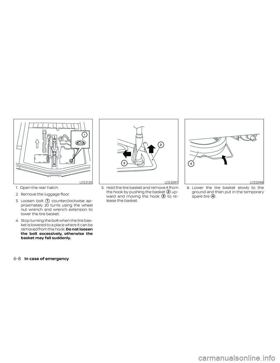
1. Open the rear hatch.
2. Remove the luggage floor.
3. Loosen bolt
�1counterclockwise ap-
proximately 20 turns using the wheel
nut wrench and wrench extension to
lower the tire basket.
4. Stop turning the bolt when the tire bas- ket is lowered to a place where it can be
removed from the hook. Do not loosen
the bolt excessively, otherwise the
basket may fall suddenly. 5. Hold the tire basket and remove it from
the hook by pushing the basket
�2up-
ward and moving the hook
�3to re-
lease the basket. 6. Lower the tire basket slowly to the
ground and then put in the temporary
spare tire�4.
LCE2125LCE2097LCE2098
6-8In case of emergency
Page 224 of 330
7. Reinstall the tire basket by pushing up-ward on the basket
�5and inserting the
hook
�6. Please be sure that the hook is located as
shown in the image�7. The hook must
engage from the inside of the basket. 8. Tighten the bolt�8clockwise until the
bolt is tight using the wheel nut wrench
and wrench extension to move the tire
basket up to the holding position.
WARNING
∙ Always make sure that the spare tire, tire basket and jacking equipment are
properly secured af ter use. Such
items can become dangerous projec-
tiles in an accident or sudden stop.
LCE2099LCE2100LCE2126
In case of emergency6-9
Page 225 of 330

∙ The spare tire is designed for emer-gency use. For additional information
refer to “Wheels and tires” in the “Do-
it-yourself ” section of this manual.
∙ When reinstalling the spare tire bas- ket under the vehicle af ter use, be
sure that the hook engages the bas-
ket from the inside. If the spare tire
basket hook is not engaged properly,
there is an increased risk of the spare
tire separating from the vehicle in a
crash and causing injury.
Stowing the damaged tire
Securely store the damaged tire in the
cargo area.
Securely store the jack and tools in the
storage area.
Return the spare tire basket back to its origi-
nal position in the reverse order of removal.
For additional information, refer to “Getting
the spare tire and tools” in this section.
NOTE:
The spare tire basket cannot be used to
store the conventional tire.
WARNING
∙ Always make sure that the spare tireand jacking equipment are properly
secured af ter each use. Such items
can become dangerous projectiles in
an accident or sudden stop.
∙ Make sure that the spare tire basket is properly secured in its original posi-
tion af ter removing the spare tire.
∙ The spare tire and small size spare tire are designed for emergency use. For
additional information, refer to
“Wheels and tires” in the “Do-it-
yourself ” section of this manual.
LCE2248
6-10In case of emergency
Page 265 of 330

HEADLIGHT AIM
The aim of the headlights may require ad-
justment when replacing the headlight as-
sembly or when the vehicle’s front body
has been repaired. When the adjustment is
required, follow these procedures, or have
them adjusted by a NISSAN dealer.
Before performing the headlights aim ad-
justment:∙ Check the pressure of all tires for the correct inflation pressure.
∙ Check that the tools and spare tire are stowed securely. ∙ Check that the fuel and lubricants levels
are filled to correct capacities.
∙ Unload all luggage and other items, which may influence the vehicle’s
height level.
∙ Load a weight on the driver’s seat that is equivalent to the weight of a driver.
Stopping the vehicle
1. Park the vehicle on a level surface verti-
cal to the wall or screen to which the
headlights will be projected.
2. Move the vehicle close to the wall to determine the point P as shown in the
illustration.
The point P must be:
“H” is the distance between the head-
light’s center point to the level surface.
“WL” is the distance between the lef t
and right headlights’ centers.
LDI2422LDI2423
8-24Do-it-yourself
 is
shif ted to P (Park) or the manual
transmission (if so equipped) is
shif ted to R (Rever")