Page 123 of 330

WARNING
∙ Gasoline is extremely flammable andhighly explosive under certain condi-
tions. You could be burned or seri-
ously injured if it is misused or mis-
handled. Always stop the engine and
do not smoke or allow open flames or
sparks near the vehicle when
refueling.
∙ Do not attempt to top off the fuel tank af ter the fuel pump nozzle shuts off
automatically. Continued refueling
may cause fuel overflow, resulting in
fuel spray and possibly a fire.
∙ Use only an original equipment type fuel-filler cap as a replacement. It has
a built-in safety valve needed for
proper operation of the fuel system
and emission control system. An in-
correct cap can result in a serious mal-
function and possible injury. It could
also cause the Malfunction Indicator
Light (MIL) to come on.
∙ Never pour fuel into the throttle body to attempt to start your vehicle. ∙ Do not fill a portable fuel container in
the vehicle or trailer. Static electricity
can cause an explosion of flammable
liquid, vapor or gas in any vehicle or
trailer. To reduce the risk of serious
injury or death when filling portable
fuel containers:
– Always place the container on the ground when filling.
– Do not use electronic devices when filling.
– Keep the pump nozzle in contact with the container while you are
filling it.
– Use only approved portable fuel containers for flammable liquid.
CAUTION
∙ Do not use a fuel containing morethan 15% ethanol in your vehicle. For
additional information, refer to “Fuel
Recommendation” in the “Technical
and consumer information” section of
this manual. ∙ Failure to tighten the fuel-filler cap
properly may cause the
Mal-
function Indicator Light (MIL) to illumi-
nate. If the
light illuminates be-
cause the fuel-filler cap is loose or
missing, tighten or install the cap and
continue to drive the vehicle.
The
light should turn off af ter a
few driving trips. If the
light does
not turn off af ter a few driving trips,
have the vehicle inspected. It is rec-
ommended that you visit a NISSAN
dealer for this service.
∙ The LOOSE FUEL CAP warning mes- sage will be displayed if the fuel-filler
cap is not properly tightened. It may
take a few driving trips for the mes-
sage to be displayed. Failure to
tighten the fuel-filler cap properly af-
ter the LOOSE FUEL CAP warning mes-
sage is displayed/warning appears
may cause the
Malfunction Indi-
cator Light (MIL) to illuminate.
∙ For additional information, refer to the “Malfunction Indicator Light (MIL)”
in the “Instruments and controls” sec-
tion of this manual.
3-12Pre-driving checks and adjustments
Page 124 of 330
∙ If fuel is spilled on the vehicle body,flush it away with water to avoid paint
damage.
For additional information, refer to “Fuel
Recommendation” in the “Technical and
consumer information” section of this
manual.
LOOSE FUEL CAP warning
message
The LOOSE FUEL CAP warning message
displays in the odometer when the fuel-
filler cap is not tightened correctly af ter the
vehicle has been refueled. It may take a few
driving trips for the message to be dis-
played. To turn off the warning message,
do the following: 1. Remove and install the fuel-filler cap as previously described as soon as pos-
sible.
2. Tighten the fuel-filler cap until a single click is heard. 3. Press the loose fuel cap warning reset
button
�Ain the meter for about 1 sec-
ond to turn off the LOOSE FUEL CAP
warning message af ter tightening the
fuel-filler cap.
LIC2468
Pre-driving checks and adjustments3-13
Page 125 of 330
TILT OPERATION
Pull the lock lever down�1and adjust the
steering wheel up or down
�2to the de-
sired position.
Push the lock lever up
�1to lock the steer-
ing wheel in place.
WARNING
Do not adjust the steering wheel while
driving. You could lose control of your
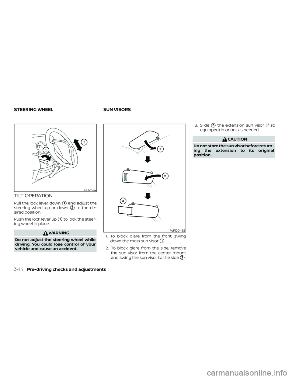
vehicle and cause an accident. 1. To block glare from the front, swing
down the main sun visor�1.
2. To block glare from the side, remove the sun visor from the center mount
and swing the sun visor to the side
�2. 3. Slide
�3the extension sun visor (if so
equipped) in or out as needed.
CAUTION
Do not store the sun visor before return-
ing the extension to its original
position.
LPD2674
WPD0435
STEERING WHEEL SUN VISORS
3-14Pre-driving checks and adjustments
Page 126 of 330
VANITY MIRRORS (if so equipped)
To access the vanity mirror, pull the sun
visor down and flip open the mirror cover.
CARD HOLDER (driver’s side only)
(if so equipped)
To access the card holder, pull the sun visor
down and slide card in the card holder
�A.
Do not view information while operating
the vehicle.
REARVIEW MIRROR
The night position�1reduces glare from
the headlights of vehicles behind you at
night.
Use the day position
�2when driving in
daylight hours.
WARNING
Use the night position only when neces-
sary, because it reduces rear view
clarity.
LPD2586LPD2033WPD0126
MIRRORS
Pre-driving checks and adjustments3-15
Page 127 of 330
OUTSIDE MIRRORS
WARNING
∙ Objects viewed in the outside mirroron the passenger side are closer than
they appear. Be careful when moving
to the right. Using only this mirror
could cause an accident. Use the in-
side mirror or glance over your shoul-
der to properly judge distances to
other objects.
∙ Do not adjust the mirrors while driv- ing. You could lose control of your ve-
hicle and cause an accident.
Manual control type (if so
equipped)
The outside mirror can be moved in any
direction for a better rear view by adjusting
the inside lever.
Electric control type (if so
equipped)
The outside mirror remote control will op-
erate only when the ignition switch is in the
ACC or ON position.
Move the small switch
�1to select the right
or lef t mirror. Adjust each mirror to the de-
sired position using the large switch
�2.
Move the small switch to the center (neu-
tral) position to prevent accidentally mov-
ing the mirror.
LPD2168LPD0237
3-16Pre-driving checks and adjustments
Page 128 of 330
WARNING
∙ Objects viewed in the outside mirroron the passenger side are closer than
they appear. Be careful when moving
to the right. Using only this mirror
could cause an accident. Use the in-
side mirror or glance over your shoul-
der to properly judge distances to
other objects.
∙ Do not adjust the mirrors while driv- ing. You could lose control of your ve-
hicle and cause an accident.
Manual folding outside mirrors
Pull the outside mirror toward the door to
fold it.
Heated mirrors (if so equipped)
The outside mirrors can be heated to de-
frost, defog, or de-ice for improved visibility.
For additional information, refer to “Rear
window and outside mirror (if so equipped)
defroster switch” in the “Instruments and
controls” section of this manual.
WPD0056
Pre-driving checks and adjustments3-17
Page 132 of 330

WARNING
∙ Failure to follow the warnings and in-structions for proper use of the Rear-
View Monitor system could result in
serious injury or death.
∙ RearView Monitor is a convenience feature and is not a substitute for
proper backing. Always turn and look
out the windows and check mirrors to
be sure that it is safe to move before
operating the vehicle. Always back up
slowly.
∙ The system is designed as an aid to the driver in showing large stationary
objects directly behind the vehicle, to
help avoid damaging the vehicle.
∙ The distance guide line and the ve- hicle width line should be used as a
reference only when the vehicle is on a
level paved surface. The distance
viewed on the monitor is for reference
only and may be different than the
actual distance between the vehicle
and displayed objects.
CAUTION
Do not scratch the camera lens when
cleaning dirt or snow from the front of
the camera.
The RearView Monitor system automati-
cally shows a rear view of the vehicle when
the shif t lever is shif ted into the R (Reverse)
position. The radio can still be heard while
the RearView Monitor is active.
To display the rear view, the RearView Moni-
tor system uses a camera located on the
rear hatch near the handle
�1.
REARVIEW MONITOR SYSTEM
OPERATION
With the ignition switch in the ON position,
move the shif t lever to the R (Reverse) po-
sition to operate the RearView Monitor.
LHA4623
Heater, air conditioner, audio and phone systems4-3
Page 135 of 330
.
2. Press t")
object when backing up to the position�A
if the object projects over the actual back-
ing up course.
ADJUSTING THE SCREEN
1. Firmly apply the brake and place theshif t lever in R (reverse).
2. Press the ENTER/SETTING button.
3. The screen will display the Brightness settings.
4. Turn the TUNE/FOLDER knob to adjust the setting up or down.
5. Press the ENTER/SETTING button again to display the Contrast settings.
6. Turn the TUNE/FOLDER knob to adjust the setting up or down. 7. Press the ENTER/SETTING button to
complete the adjustment.
NOTE:
Do not adjust any of the display settings
of the RearView Monitor while the ve-
hicle is moving. Make sure the parking
brake is firmly applied.
REARVIEW MONITOR SYSTEM
LIMITATIONS
WARNING
Listed below are the system limitations
for RearView Monitor. Failure to operate
the vehicle in accordance with these
system limitations could result in seri-
ous injury or death.
∙ The system cannot completely elimi- nate blind spots and may not show
every object.
∙ Underneath the bumper and the cor- ner areas of the bumper cannot be
viewed on the RearView Monitor be-
cause of its monitoring range limita-
tion. The system will not show small
objects below the bumper, and may
not show objects close to the bumper
or on the ground.LHA3639
4-6Heater, air conditioner, audio and phone systems


To access the vanity mirror, pull the sun
visor down and flip open the mirror cover.
CARD HOLDER (driver’s side only)
(if so equipped)
To access the card holder, pull")

