Page 90 of 435
Speedometer
The speedometer indicates vehicle speed.Odometer/Twin trip odometer
The odometer and the twin trip odometer
�1are displayed in the vehicle information
display (Type A) (if so equipped) or the trip
computer (Type B) (if so equipped) when
the ignition switch is placed in the ON po-
sition.
The odometer records the total distance
the vehicle has been driven.
The twin trip odometer records the dis-
tance of individual trips. Changing the display
Push the TRIP RESET switch
�2on the right
side of the instrument panel to change the
display as follows:
Trip
→ Trip→ Odometer Mile-
age →Trip
LIC2255
Type A (if so equipped)
LIC3584
Type B (if so equipped)
LIC3595
2-6Instruments and controls
Page 93 of 435

When the ignition switch is placed in the ON
position, modes of the trip computer can
be selected by pushing the TRIP RESET
switch
�A.
Each time the TRIP RESET switch is")
TRIP COMPUTER (if so equipped)
When the ignition switch is placed in the ON
position, modes of the trip computer can
be selected by pushing the TRIP RESET
switch
�A.
Each time the TRIP RESET switch is pushed,
the display changes as follows:
Trip A →Trip B →Odometer
The
switch for the trip computer is
located on the lower lef t side of the instru-
ment panel. Each time the
switch is pushed, the
display will change as follows:
Average fuel economy →Average speed →
Trip time →Trip Distance
Average fuel economy (mpg or
km/l)
The average fuel economy mode shows
the average fuel economy since the last
reset. Resetting is done by pressing the
change/reset switch for more than ap-
proximately 1 second. The display is up-
dated every 30 seconds. At about the first
1/3 mi (500 m) af ter a reset, the display
shows (----).
Average speed (mph or km/h)
The average speed mode shows the aver-
age vehicle speed since last reset. Reset-
ting is done by pressing the change/reset
switch for more than approximately 1 sec-
ond. The display is updated every 30 sec-
onds. The first 30 seconds af ter a reset, the
display shows (----).
Trip time
The trip time mode shows the time since
the last reset. The displayed time can be
reset by pressing the change/trip switch
for more than approximately 1 second.
Trip distance
The trip distance mode shows the distance
traveled since the last reset. The trip dis-
tance can be reset by pressing the
change/trip switch for more than approxi-
mately 1 second.
Shipping mode
This message may appear if the extended
storage switch is not pushed in. When this
message appears, push in the extended
storage switch to turn off the warning. For
additional information, refer to “Extended
storage switch” in this section.
LIC3594
Instruments and controls2-9
Page 106 of 435

�3— Returns to the previous menu.
The OK,
andbuttons also
control audio and control panel functions
in some conditions. Most screens and
menus offer instruction prompts of the
steering switch buttons to indicate how to
control the vehicle information display.
Dots on the lef t side of the vehicle informa-
tion display will appear if there is more than
one page of menu items. The OK button
changes the audio source and
the
buttons also control voice
recognition manual mode. For additional
information, refer to the separate
NissanConnect® Owner’s Manual.
STARTUP DISPLAY
When the vehicle in placed in the ON posi-
tion the screens that display in the vehicle
information display include:
∙ Gauges
∙ Audio
∙ Navigation
∙ Fuel Economy
∙ Drive Computer
∙ Warning Review
∙ Settings
For additional information on warnings
and indicators, refer to “Vehicle information
display warnings and indicators” in this
section.
To control what items display in the vehicle
information display, refer to “Customize
display” in this section.
SETTINGS
The setting mode allows you to change the
information displayed in the vehicle infor-
mation display as well as the model for
several vehicle functions: ∙ Driver Assistance
∙ Customize Display
∙ Vehicle Settings
∙ TPMS Settings
∙ Maintenance
∙ Clock
∙ Unit/Language
∙ Factory Reset
2-22Instruments and controls
Page 117 of 435

This indicator appears when the steering
lock cannot be released.
If this indicator appears, push the ignition
switch while lightly turni")
Steering lock release malfunction indi-
cator (if so equipped)
This indicator appears when the steering
lock cannot be released.
If this indicator appears, push the ignition
switch while lightly turning the steering
wheel right and lef t.
Illumination indicator
This indicator shows the illumination ad-
justment of the instrument panel. For addi-
tional information, refer to “Instrument
brightness control” in this section.
Transmission Shif t Position indicator (if
so equipped)
This indicator shows the transmission shif t
position.
High Coolant Temp: See Owner’s Manual
This warning appears when the tempera-
ture of the engine coolant is too high. Stop
the vehicle in a safe location as soon as
possible. Avoid quick starting or abrupt ac-
celeration. When the warning turns off, the
vehicle can be driven.If the warning appears again soon af ter it
turns off, have the vehicle checked. It is rec-
ommended that you visit a NISSAN dealer
for this service.
Outside Temperature Display
The outside temperature display appears
in the center region of the vehicle informa-
tion display.
Low Outside Temperature
This warning appears if the outside tem-
perature is below 37°F (3°C). The tempera-
ture can be changed to display in Celsius or
Fahrenheit. For additional information, re-
fer to “Settings” in this section.
Oil and Filter
This indicator appears when the customer
set distance comes for changing the en-
gine oil and filter. You can set or reset the
distance for checking or replacing these
items. For scheduled maintenance items
and intervals, refer to the “Maintenance and
schedules” section of this manual.
Tire
This indicator appears when the customer
set distance is reached for replacing tires.
You can set or reset the distance for replac-
ing tires.WARNING
The tire replacement indicator is not a
substitute for regular tire checks, includ-
ing tire pressure checks. For additional in-
formation, refer to “Changing wheels and
tires” in the “Do-it-yourself ” section of
this manual. Many factors including tire
inflation, alignment, driving habits and
road conditions affect tire wear and when
tires should be replaced. Setting the tire
replacement indicator for a certain driv-
ing distance does not mean your tires will
last that long. Use the tire replacement
indicator as a guide only and always per-
form regular tire checks. Failure to per-
form regular tire checks, including tire
pressure checks could result in tire failure.
Serious vehicle damage could occur and
may lead to a collision, which could result
in serious personal injury or death.
Other
This indicator appears when the customer
set distance is reached for checking or re-
placing maintenance items other than the
engine oil, oil filter and tires. Other mainte-
nance items can include such things as air
filter or tire rotation. The distance for
checking or replacing the items can be set
or reset.
Instruments and controls2-33
Page 125 of 435
HEADLIGHT CONTROL SWITCH
Lighting
�1Rotate the switch to theposition,
and the side, tail, license plate, and in-
strument panel lights will come on.
�2Rotate the switch to theposition,
and the headlights will come on and all
the other lights remain on.
CAUTION
Use the headlights with the engine run-
ning to avoid discharging the vehicle
battery.
Type A (if so equipped)
LIC2634
Type B (if so equipped)
LIC4008
Type C (if so equipped)
LIC4007
HEADLIGHT AND TURN SIGNAL
SWITCH
Instruments and controls2-41
Page 126 of 435

The autolight system allows the headlights
to turn on and off automatically. The auto-
light system can:∙ Turn on the headlights, front parking, tail, license plate")
Autolight system (if so equipped)
The autolight system allows the headlights
to turn on and off automatically. The auto-
light system can:∙ Turn on the headlights, front parking, tail, license plate and instrument panel
lights automatically when it is dark.
∙ Turn off all the lights when it is light.
∙ Keep all the lights on for a period of time af ter you place the ignition switch in the
OFF position and all doors are closed. To turn on the autolight system:
1. Turn the headlight switch to the AUTO position
�1.
2. Place the ignition switch in the ON po- sition.
3. The autolight system automatically turns the headlights on and off.
Initially, if the ignition switch is turned off
and a door is opened and lef t open, the
headlights remain on for a period of time. If
another door is opened while the head-
lights are on, then the timer is reset.
To turn the autolight system off, turn the
switch to the OFF,
,orposition.
NOTE:
Autolight activation sensitivity and the
time delay for autolight shutoff may be
able to be adjusted. For additional infor-
mation, refer to “Vehicle information dis-
play ” in this section. Be sure you do not put anything on top
of the autolight sensor located in the top
side
�1of the instrument panel. The au-
tolight sensor controls the autolight; if it
is covered, the autolight sensor reacts as
if it is dark out and the headlights will
illuminate. If this occurs while parked
with the engine off and the ignition
switch placed in the ON position, your
vehicle’s battery could become dis-
charged.
LIC2636LIC4006
2-42Instruments and controls
Page 128 of 435
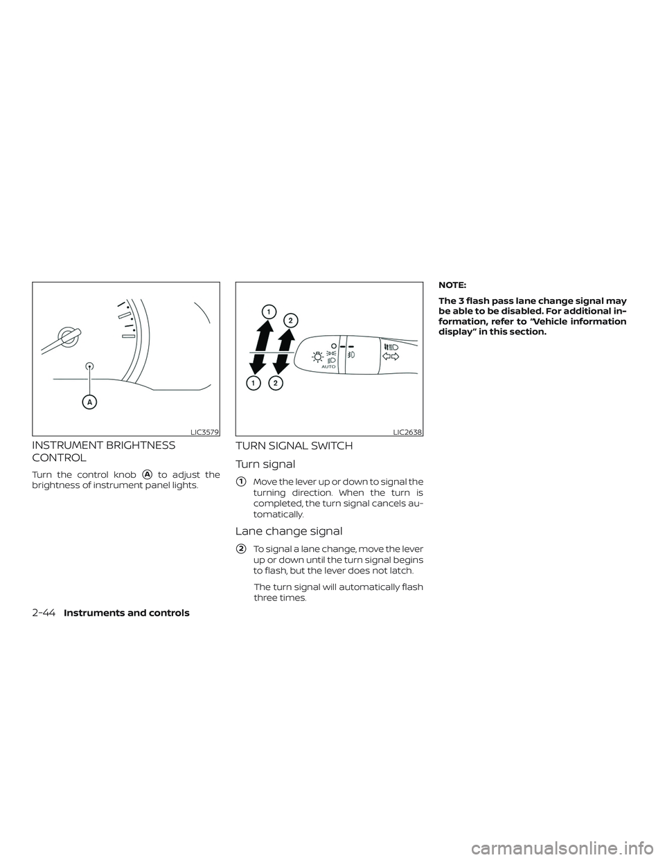
INSTRUMENT BRIGHTNESS
CONTROL
Turn the control knob�Ato adjust the
brightness of instrument panel lights.
TURN SIGNAL SWITCH
Turn signal
�1Move the lever up or down to signal the
turning direction. When the turn is
completed, the turn signal cancels au-
tomatically.
Lane change signal
�2To signal a lane change, move the lever
up or down until the turn signal begins
to flash, but the lever does not latch.
The turn signal will automatically flash
three times. NOTE:
The 3 flash pass lane change signal may
be able to be disabled. For additional in-
formation, refer to “Vehicle information
display ” in this section.
LIC3579LIC2638
2-44Instruments and controls
Page 131 of 435

The vehicle should be driven with the VDC
system on for most driving conditions.
If the vehicle is stuck in mud or snow, the
VDC system reduces the engine output to
reduce wheel spin. The engine speed will
be reduced even if the accelerator is de-
pressed to the floor. If maximum engine
power is needed to free a stuck vehicle,
turn the VDC system off.
To turn off the VDC system, push the VDC
OFF switch. The
indicator and the Au-
tomatic Emergency Braking (AEB) system
warning light will come on. Push the VDC OFF switch again or restart
the engine to turn on the system. For addi-
tional information, refer to “Vehicle Dy-
namic Control (VDC) system” in the “Start-
ing and driving” section of this manual.
12V OUTLETS
The power outlet is for powering electrical
accessories such as cellular telephones. It
is rated at 12 volt, 120W (10A) maximum.
The front console power outlet is powered
only when the ignition switch is in the ON
position, or while the accessory power is
active.
LIC3344
Instrument Panel
LIC4003
VEHICLE DYNAMIC CONTROL (VDC)
OFF SWITCH
POWER OUTLETS
Instruments and controls2-47