2018 MITSUBISHI OUTLANDER III ECO mode
[x] Cancel search: ECO modePage 64 of 441

Supplemental Restraint System (SRS) - airbag
Seat and restraint systems 4-35
4
cuts, tears, increase in thickness in any sec-tion of the webbing from broken fibers, orsevere fading from sunlig
ht. All of these con-
ditions indicate a weakening of the belt,which may adversely affe
ct seat belt perfor-
mance in an accident.
N00407701889
This vehicle is equippe
d with a Supplemental
Restraint System (SRS), which includes air-bags for the driver and passengers.The SRS front airbags are designed to supple-ment the primary protection of the driver andfront passenger seat belt systems by provid-ing those occupants w
ith protection against
head and chest injuries
in certain moderate to
severe frontal collisi
ons. The SRS front air-
bags, together with sensors at the front of thevehicle and sensors attached to the frontseats, form an advanced airbag system.The SRS driver’s knee airbag is designed tosupplement the primary protection of thedriver’s seat belt system. It can reduce theforward movement of the driver’s lower legsand provide increased
overall body protection
in certain moderate to
severe frontal colli-
sions.The SRS side airbags and the curtain airbagsare also designed to supp
lement the seat belts.
The SRS side airbags provide the driver andfront passenger with pr
otection against chest
injuries by deploying the bag on the sideimpacted in moderate
to severe side impact
collisions. The SRS curtain airbags provide
the driver and the passengers on the front seatand the second row outboard seats with pro-tection against head injuries by deploying thecurtain airbag on the si
de impacted in moder-
ate to severe side imp
act collisions and by
deploying both curtain
airbags when a roll-
over is detected. The curtain airbags are alsodesigned to help reduce the risk of completeand partial ejection fro
m the vehicle through
side windows in both side impact and roll-over type accidents.The SRS airbags are NOT a substitute for useof the seat belts. For maximum protection inall types of accident
s, seat belts must
ALWAYS be worn by everyone who drives orrides in this vehicle
(with infants and small
children in an appropriate child restraint sys-tem in the rear seat, and older children buck-led in the rear seat). Refer to “Child restraintsystems” on page 4-27.
WA R N I N GDo not attempt to repair or replace anypart of the seat belt assemblies. This workshould be done
by an authorized
Mitsubishi Motors dealer. Failure to havean authorized Mits
ubishi Motors dealer
perform the work could reduce the effec-tiveness of the belts and could result in aserious injury or de
ath in an accident.
Never use an organic solvent to clean theseat belt webbing. Do not attempt tobleach or re-dye th
e seat belt webbing.
These may weaken the
seat belt webbing,
increasing risk of in
jury or death in an
accident.Clean seat belt webbing only with mildsoap or detergent solution and rinse itwith lukewarm water, and dry the seatbelt webbing completely before retractingit.
Supplemental Restraint Sys-tem (SRS) - airbag
BK0249100US.book 35 ページ 2017年5月10日 水曜日 午前8時49分
Page 67 of 441

Supplemental Restraint System (SRS) - airbag4-38 Seat and restraint systems
4
N00407801532
The SRS includes the following components:
The airbag control unit monitors the readinessof the electronic parts of the system wheneverthe ignition switch or the operation mode isunder the following conditions. These includeall of the items listed
above and all related
wiring.[Except for vehicles
equipped with the
F. A . S . T. - k e y ]The ignition switch is in the “ON” or“START” position.[Vehicles equipped with the F.A.S.T.-key]The operation mode is in ON.The airbags will opera
te under the same con-
ditions as the airbag control unit.
When the impact sensors detect a sufficientfront or side impact to deploy the airbag(s),the appropriate airbag
(s) will be deployed.
When the airbag control unit detects rolloverof the vehicle, curtain airbags will bedeployed.When airbags deploy, so
me smoke is released
accompanied by a loud noise. The smoke isnot harmful, but do not intentionally inhalethe smoke as it may ca
use temporary irrita-
tion to people with respiratory problems.An inflated airbag will deflate quickly, so youmay not even notice that the airbag wasinflated.Airbag inflation does not prevent the driverfrom seeing or being able to steer the vehicle,and does not prevent people from leaving thevehicle.
N00418601266
This vehicle is equipped with an event datarecorder (EDR).
How the Supplemental Restraint System works 1- Airbag module (Driver)2- SRS warning light3- Passenger’s airbag off indicator4- Front impact sensors5- Airbag module (Passenger)6- Airbag module (Driver’s knee)7- Driver’s seat position sensor8- Passenger’s seat oc
cupant classifica-
tion sensor system
9- Airbag control unit
10- Side airbag modules11- Curtain airbag modules12- Side impact sensors
CAUTIONAirbags inflate very quickly and with greatforce. In certain situ
ations, contact with an
inflating airbag may cause small cuts, abra-sions, and bruises.
Event Data Recording
BK0249100US.book 38 ページ 2017年5月10日 水曜日 午前8時49分
Page 69 of 441

Supplemental Restraint System (SRS) - airbag4-40 Seat and restraint systems
4
bag control unit controls deployment of thepassenger’s front airbag in accordance withthe information it receives from this system.The passenger’s front airbag will not deployin an impact when the system senses no occu-pant on the front passenger’s seat or a child ina child restraint system. In this case, the pas-senger airbag off indi
cator will come on.
Refer to “Passenger’s ai
rbag off indicator” on
page 4-40.If there is a problem involving the passen-ger’s seat occupant cl
assification sensor sys-
tem, the SRS warning light in the instrumentpanel will come on. Refer to “SRS warninglight/display” on page 4-41.
N00418101346
The passenger’s airbag off indicator islocated in the instrument panel.The indicator normally comes on when theignition switch is turned to the “ON” positionor the operation mode is put in ON, and goesout a few seconds later.
In the following situ-
ations, the indicator will stay on to show thatthe passenger front airb
ag is not operational.
The front passenger’s seat is not occupied.
WA R N I N GIf any of the follow
ing conditions occur,
you should immediatel
y have your vehicle
inspected by an au
thorized Mitsubishi
Motors dealer as soon as possible:• The SRS warning light does not initiallycome on when the ignition switch or theoperation mode is under the followingconditions.[Except for vehicles equipped with theF. A . S . T. - k e y ]The ignition switch is in the “ON” or“START” position.[Vehicles equipped with the F.A.S.T.-key]The operation mode is in ON.• The SRS warning light does not go outafter several seconds.
• The SRS warning li
ght comes on while
you are driving.
To ensure that the passenger’s seat occu-pant classification sensor system can sensecorrectly, observe the following instruc-tions. Failure to follow these instructionscan adversely affect
the performance of
the passenger’s airbag system.• Adjust the seat to the correct position,and sit well back
against the seatback.
Refer to “Front seats” on page 4-4.• Do not recline the seatback more thannecessary.• Never have more th
an one person (adult
or child) sitting on the seat.• Do not place anything between the seatand the floor console.• When attaching a child restraint system,secure it firmly.• Do not place luggage or other objects onthe seat.• Do not use a seat cover or a cushion.• Do not modify or re
place the seat and
seat belt.• Do not place luggage or other objectsunder the seat.• Do not place and use
an electronic device
such as a computer on the seat.• Do not place heavy obje
cts on the seat or
stick pins, needles, or other objects intoit.• Do not remove the seat cushion skin.WA R N I N G
• If any liquid is spilled on the seat, wipe itand dry the seat immediately.
If the vehicle is involved in a severeimpact, have the SRS sensors inspected byan authorized
Mitsubishi Motors dealer as
soon as possible.
Passenger’s airbag off indicator
WA R N I N G
BK0249100US.book 40 ページ 2017年5月10日 水曜日 午前8時49分
Page 83 of 441

5
Features and controlsInformation screen display (Vehicle equipped with the mul
ti information display - Type 1)
.................................................................................................. 5-206Combination headlights and dimmer switch ............................... 5-207Headlight leveling switch (if so equipped) .................................. 5-216Turn signal lever .......................................................................... 5-217Hazard warning flasher switch .................................................... 5-218ECO mode switch ........................................................................ 5-218Front fog light switch (if so equipped) ......................................... 5-218Wiper and washer switch ............................................................ 5-219Wiper deicer switch (if so equipped)............................................ 5-224Electric rear window def
ogger switch ......
...........
...........
............. 5-225
Heated steering wheel switch (if so equipped)............................. 5-226Horn switch ................................................................................. 5-227Link System ................................................................................. 5-227USB input terminal ...................................................................... 5-227Sun visors .................................................................................... 5-22912 V power outlets ...................................................................... 5-230HomeLink
® Wireless Control System (if so equipped) ............... 5-231
Interior lights ............................................................................... 5-236Storage spaces ............................................................................. 5-239Cup holders ................................................................................. 5-242Bottle holders .............................................................................. 5-243Cargo area cover (if so equipped) ............................................... 5-244Assist grips .................................................................................. 5-246Coat hooks ................................................................................... 5-246Luggage hooks ............................................................................ 5-246BK0249100US.book 2 ページ 2017年5月10日 水曜日 午前8時49分
Page 91 of 441

Keyless entry system (if so equipped)5-10 Features and controls
5
N00543701060
If you are near your vehicle and feel threat-ened, you may activate the alarm to call atten-tion as follows:1. Press the PANIC button (3) for more than1 second.2. The headlights will blink on and off andthe horn will sound intermittently forabout 3 minutes.3. To turn off the alarm, press any button onthe remote control transmitter.
N00543801087
Only remote control transmitters pro-grammed with the vehicle’s electronics canlock or unlock all doors and the liftgate.If you lose the remote control transmitter, youcan order a remote control transmitter fromyour authorized Mitsubishi Motors dealer byreferring to the key number.To prevent vehicle theft, the ID code for theremote control transmitter must be changed.Take your vehicle and all remote controltransmitters to your authorized MitsubishiMotors dealer to have your ID code changed.
N00543900049
To add a remote control transmitter, you mustalready have 1 regist
ered remote control
transmitter.Registering the ID code can be done by your-self or by your authorized Mitsubishi Motorsdealer. For you to regist
er the ID code your-
self, follow the “Customer remote controltransmitter programming” procedure below.If you choose to have your authorizedMitsubishi Motors dealer register the IDcode, take your vehi
cle and any remaining
keys to your authorized Mitsubishi Motorsdealer.
N00544001204
You can program new remote control trans-mitters to the system if you have one valid
(already registered) re
mote control transmit-
ter by doing the following:1. Have available al
l (current and new)
remote control transmitters you wish toregister.2. With a valid (already registered) remotecontrol transmitter, press the UNLOCKbutton (2) for 4 to 10 seconds. Then pressand hold the LOCK button (1).3. Within 10 seconds of pressing the LOCKbutton, release the LOCK and UNLOCKbuttons in sequence.At this time, ID codes for all remote con-trol transmitters except for the transmitterused in steps 2 and 3 are erased and theanswerback function (door is locked andunlocked) informs you that the registra-tion mode has been activated.4. Within 60 seconds after step 3, completethe following ID code
registration opera-
tion using the next remote control trans-mitter you wish to register within 4seconds.i) Press both the LOCK and UNLOCKbuttons for 2 seconds.ii) Release both the LOCK and UNLOCKbuttons for 1 second.iii) Press the UNLOCK button. Theanswerback function informs you that theID code registration
of the transmitter is
completed.
Using the panic alarm
Replacement remote control transmitters
Additional remote control transmitters
NOTE
You are provided with
2 remote control
transmitters, but you may register up to 8remote control transmitters.
Customer remote control trans-mitter programming (Except for vehicles sold in Canada)
BK0249100US.book 10 ページ 2017年5月10日 水曜日 午前8時49分
Page 92 of 441

Keyless entry system (if so equipped)
Features and controls 5-11
5
5. To register the ID codes of additionalremote control transmitters, repeat step 4within 60 seconds after step 4.6. If no ID code of a remote control trans-mitter is registered within 60 secondsafter step 4, the regi
stration mode is can-
celed and the normal mode returns.
N00546101124
Your keyless entry system operates on a radiofrequency subject to
Federal Communica-
tions Commission (FCC)
Rules (For vehicles
sold in U.S.A.) and Industry Canada Rules
(For vehicles sold in Canada). This devicecomplies with Part 15 of FCC Rules andIndustry Canada licenc
e-exempt RSS stan-
dard(s).Operation is subject to the following two con-ditions.This device may not
cause harmful inter-
ference.This device must ac
cept any interference
received, including interference that maycause undesired operation.
N00544101205
1. Before replacing the battery, remove staticelectricity from your body by touching ametal grounded object.
NOTE
For verification purposes, try to lock andunlock the doors after the registration iscompleted.The indicator light (4)
comes on each time a
button is pressed.The keyless entry system does not work ifthe key is in the ignition switch.The remote control tr
ansmitter can be used
from approximately 40
feet (12 m) away.
However, this distan
ce may change if your
vehicle is near a TV transmitting tower, apower station, or a radio station.If the UNLOCK button (2) is pressed whenall doors and the liftgate are locked and nodoors or the liftgate are opened withinapproximately 30 seconds, the doors and theliftgate will automatically re-lock.On a vehicle equipped with the SmartphoneLink Display Audio, the functions can beadjusted on the screen. For details, refer tothe separate owner’s manual.
If the following conditi
ons are observed after
pressing the LOCK (1) or UNLOCK (2) but-ton on the remote control transmitter, thebattery in the remote control transmitter mayneed to be replaced.• The doors and the lift
gate cannot be locked
or unlocked.• The panic alarm cannot be operated.• The indicator light
(4) is dim or does not
come on.
If you lose your remote control transmitter,please contact an au
thorized Mitsubishi
Motors dealer for a replacement.If you wish to obtain
an additional remote
control transmitter, please contact an autho-rized Mitsubishi Moto
rs dealer. A maximum
of 8 remote control tr
ansmitters can be pro-
grammed for your vehicle.To use the new remote control transmitters, itis necessary to register
the key with both the
electronic immobilizer and keyless entry sys-tem.Also refer to “Electronic immobilizer (Anti-theft starting system): Customer key pro-gramming” on page 5-6.
General information
NOTE
CAUTIONChanges or modifica
tions not expressly
approved by the manufacturer for compli-ance could void the user
’s authority to oper-
ate the equipment.
Procedure for replacing the remote control transmitter bat-tery
BK0249100US.book 11 ページ 2017年5月10日 水曜日 午前8時49分
Page 93 of 441

Keyless entry system (if so equipped)5-12 Features and controls
5
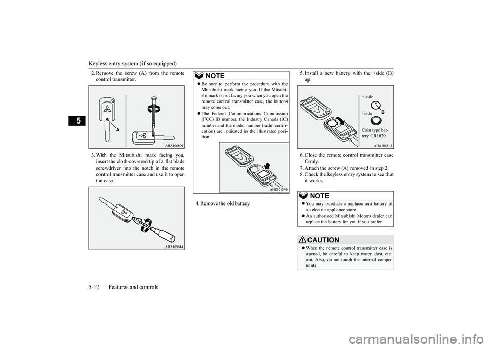
2. Remove the screw (A) from the remotecontrol transmitter.3. With the Mitsubishi mark facing you,insert the cloth-cov-ered tip of a flat bladescrewdriver into the notch in the remotecontrol transmitter case and use it to openthe case.
4. Remove the old battery.
5. Install a new battery with the +side (B)up.6. Close the remote control transmitter casefirmly.7. Attach the screw (A) removed in step 2.8. Check the keyless entry system to see thatit works.
NOTE
Be sure to perform the procedure with theMitsubishi mark facing you. If the Mitsubi-shi mark is not facing you when you open theremote control transmitter case, the buttonsmay come out.The Federal Communications Commission(FCC) ID number, the Industry Canada (IC)number and the model
number (radio certifi-
cation) are indicated in
the illustrated posi-
tion.
NOTE
You may purchase a replacement battery atan electric appliance store.An authorized Mitsubishi Motors dealer canreplace the battery for you if you prefer.CAUTIONWhen the remote control transmitter case isopened, be careful to
keep water, dust, etc.
out. Also, do not touch the internal compo-nents.
+ side- sideCoin type bat-tery CR1620
BK0249100US.book 12 ページ 2017年5月10日 水曜日 午前8時49分
Page 96 of 441

Free-hand Advanced Securi
ty Transmitter (F.A.S.T.-key) (if so equipped)
Features and controls 5-15
5
N00503301077
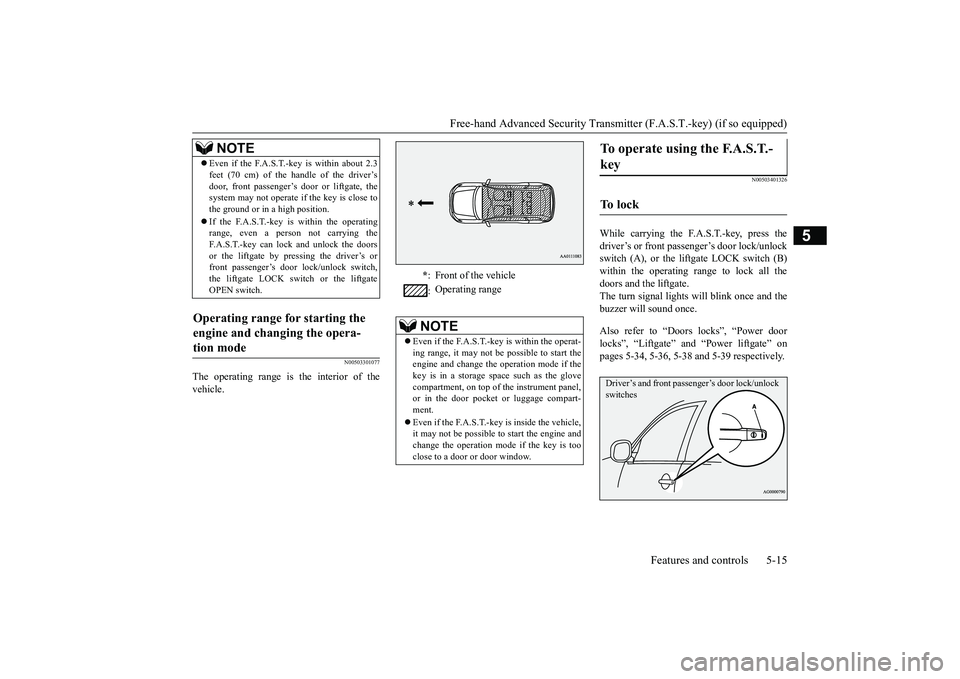
The operating range is the interior of thevehicle.
N00503401326
While carrying the F.A.S.T.-key, press thedriver’s or front passenger’s door lock/unlockswitch (A), or the liftgate LOCK switch (B)within the operating range to lock all thedoors and the liftgate.The turn signal lights will blink once and thebuzzer will sound once.Also refer to “Doors locks”, “Power doorlocks”, “Liftgate” and “Power liftgate” onpages 5-34, 5-36, 5-38 and 5-39 respectively.
Even if the F.A.S.T.-key is within about 2.3feet (70 cm) of the handle of the driver’sdoor, front passenger’s door or liftgate, thesystem may not operate if the key is close tothe ground or in a high position.If the F.A.S.T.-key is within the operatingrange, even a person not carrying theF.A.S.T.-key can lock and unlock the doorsor the liftgate by pressing the driver’s orfront passenger’s door lock/unlock switch,the liftgate LOCK switch or the liftgateOPEN switch.
Operating range for starting the engine and changing the opera-tion mode
NOTE
*: Front of the vehicle:Operating range
NOTE
Even if the F.A.S.T.-key is within the operat-ing range, it may not be possible to start theengine and change the
operation mode if the
key is in a storage space such as the glovecompartment, on top of the instrument panel,or in the door pocket or luggage compart-ment.Even if the F.A.S.T.-key is inside the vehicle,it may not be possible to
start the engine and
change the operation mode if the key is tooclose to a door or door window.
To operate using the F.A.S.T.-key
To l o c k
Driver’s and front passenger’s door lock/unlock switches
BK0249100US.book 15 ページ 2017年5月10日 水曜日 午前8時49分