Page 445 of 562

Notes ontech nical data
Plug-in hybrid: obser vethe no tes in the Supple‐
ment. Otherwise, you may not recognize dan‐
ge rs.
Mercedes-AMG vehicles: observeth e no tes in
th e Supplement. Otherwise, you may not recog‐
nize dangers.
The data stated only appliestovehicles with
st andard equipment. You can obtain fur ther
information from an authorized Mercedes-Benz
Center.
Ve hicle electronics
Tw o-w ayradios
Note s on installing two-w ayradios
&
WARNING Risk of accident due to
improper workon two-w ayradios
The electro magneticradiation from two-w ay
ra dios can inter fere with the on-board elec‐
tronics if RF transmit ters are manipulated or
re trofitted inco rrectly.
This could jeopardize the operating saf etyof
th eve hicle.
#Yo u should ha veall workon electrical
and electronic components car ried out
at a qualified specialist workshop.
&
WARNING Risk of accident from incor‐
re ct ope ration of two-w ayradios
If yo u operate two-wa yra dios incor rectly in
th eve hicle, the electromagnetic radiation
could inter fere with the on-board electronics,
e.g.:
Rif th e two-w ayradio is not connec tedto
an exterior antenna
Rif th eex terior antenna is not cor rectly
mounted or is not of low reflection
This could jeopardies the operating saf etyof
th eve hicle.
#Ha ve the lo w-reflection exterior
antenna ins talled at a qualified special‐
ist workshop.
#When operating two-w ayradios in the
ve hicle, alw ays connect them tothe
lo w- reflection exterior antenna.
* NO
TEInva lidation of the operating per‐
mit due tofailure tocomply wi th the
instructions for ins tallation and use
The operating permit may be in validated if
th e instructions for ins tallation and use of
two-w ayradios are not obser ved.
#Only use appr oved frequency bands.
#Obser vethe maximum permissible out‐
put po wer in these frequency bands.
#Only use appr oved antenna positions.
Tech nical da ta44
3
Page 446 of 562

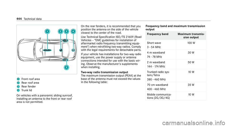
1Front roof area
2Re ar roof area
3Re ar fender
4Trunk lid
On vehicles with a panoramic sliding sunroof,
ins talling an antenna tothe front or rear roof
area is not permitted. On
there ar fende rs, it is recommended that you
position the antenna on the side of theve hicle
closest tothe center of thero ad.
Use Tech nical Specification ISO/TS 21609 (Road
Ve hicles – "EMC guidelines for ins tallation of
af te rm arke tra dio frequency transmitting equip‐
ment") when retrofitting two-w ayradios. Comply
with the legal requ irements for de tachable parts.
If yo ur vehicle has ins tallations for two-w ayradio
equipment, use the po wer supply or antenna
connections intended for use with the basic wir‐
ing. Obser vethe manufacturer's supplements
when ins talling.
Tw o-w ayradio transmission output
The maximum transmission output (PEAK) at the
base of the antenna must not exceed theva lues
in thefo llowing table: Fr
equency band and maximum transmission
output
Fr equency band Maximum transmis‐
sion output
Sho rtwa ve
3 - 54 MHz 10
0 W
4 m waveband
74 -78 MHz 30 W
2 m waveband
14 4 - 174 MHz 50 W
Tr unked radio sys‐
te m/T etra
380 - 460 MHz 10
W
70 cm waveband
400 - 460 MHz 35 W
Mobile communica‐
tions (2G/3G/4G) 10
W
444
Tech nical da ta
Page 447 of 562
Thefollowing can be used in theve hicle without
re strictions:
RRF transmitters wi tha maximum transmis‐
sion output of up to100 mW
RRF transmitters with transmitter frequencies
inthe 380 - 410 MHz frequency band and a
maximum transmission output of up to2 W
(trunked radio sy stem/T etra )
RMobile phones (2G/3G/4G)
There are no restrictions when positioning the
antenna on the outside of theve hicle for some
frequency bands.
This applies tothefo llowing frequency bands:
RTrunked radio sy stem/T etra
R70 cm waveband
R2G/3G/4G
Ve hicle identification plate, VIN and engine
number overview
Ve hicle identification plate
Vehicle identification plate (USA only)
1Perm issible grossmass
2Pe rm issible front axle load
3Perm issible rear axle load
4Pa int code
5VIN (vehicle identification number)
Tech nical da ta44
5