2018 MERCEDES-BENZ S-CLASS SEDAN change wheel
[x] Cancel search: change wheelPage 438 of 562
Thewear patte rns on the front and rear wheels
dif fer:
RFr ont wheels wear more on the shoulder of
th e tire.
RRe ar wheels wear more in the center of the
tire.
On vehicles that ha vethe same size front and
re ar wheels, inter change the wheels according
to the inter vals in the tire manufacturer's war‐
ra nty book in your vehicle documents. If this is
not available, inter change the tires every
3000 to6000 miles (5000 to10000 km),
depending on thewe ar. Ensure that the direction
of rotation is maintained.
It is impe rative toobser vethe instructions and
saf etyno tes on "Wheel change" when doing so.
Note s onstoring wheels
RAf terre moving wheels, store them in a cool,
dry and preferably dark place.
RPr otect the tires from conta ct withoil, grease
or fuel.
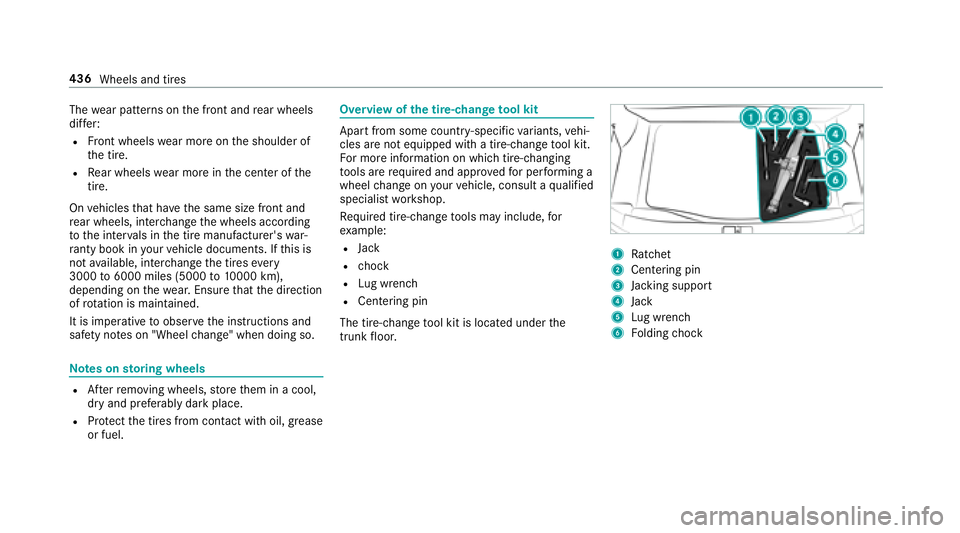
Overview of the tire-chan getool kit
Apart from some countr y-specific variants, vehi‐
cles are not equipped with a tire-change tool kit.
Fo r more information on which tire-changing
to ols are required and appr oved for per form ing a
wheel change on your vehicle, consult a qualified
specialist workshop.
Re quired tire-change tools may include, for
ex ample:
RJack
Rch ock
RLu g wrench
RCentering pin
The tire-change tool kit is located under the
trunk floor.
1Ra tchet
2Centering pin
3Jack ing support
4Jack
5Lu g wrench
6Fo lding chock
436
Wheels and tires
Page 439 of 562
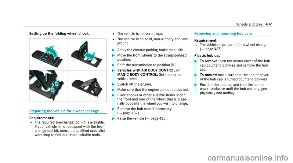
Setting upthefo lding wheel chock
Prepa ring theve hicle for a wheel change
Re quirements:RThe requ ired tire-change tool kit is available.
If yo ur vehicle is not equipped with the tire-
ch ange tool kit, consult a qualified specialist
wo rkshop tofind out about suitable tools.
RThe vehicle is not on a slope.
RThe vehicle is on solid, non-slippery and le vel
ground .
#Applythe electric parking brake manually.
#Mo vethe front wheels tothest ra ight-ahead
position.
#Shift the transmission toposition j.
#Vehicles with AIR BODY CONT ROL or
MAGIC BODY CONT ROL:Set the normal
ve hicle le vel.
#Swit choff the engine.
#Make sure that the engine cannot bestar ted.
#Place choc ks orother suitable items under
th e front and rear of the wheel that is diago‐
nally opposite the wheel youwish tochange.
#Re mo vethe hub caps if necessary
(→page 437).
#Ra ise theve hicle (→page 438).
Re moving and mounting hub caps
Requirement:RThe vehicle is prepared for a wheel change
(→page 437).
Plast ic hub cap
#Toremo ve:turn the center co ver of the hub
cap counter-clockwise and remo vethe hub
cap.
#To mount: makesurethat the center co ver
of the hub cap is turned counter-clockwise.
#Po sition the hub cap and turn the center
co ver clockwise until the hub cap engages
ph ysically and audibly.
Wheels and tires 437
Page 440 of 562
Aluminum hub cap
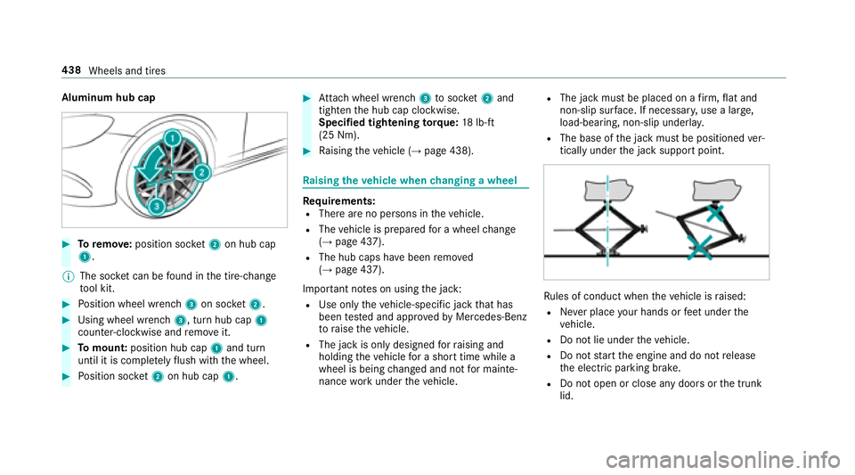
#Toremo ve:position soc ket2 on hub cap
1.
% The soc ket can be found inthe tire-change
to ol kit.
#Po sition wheel wrench 3on soc ket2.
#Using wheel wrench 3, turn hub cap1
counter-clo ckwise and remo veit.
#To mount: position hub cap 1and turn
until it is compl etely flush withth e wheel.
#Po sition soc ket2 on hub cap 1.
#Attach wheel wrench 3tosoc ket2 and
tighten the hub cap clockwise.
Specified tightening torq ue: 18lb-ft
(25 Nm).
#Ra ising theve hicle (→page 438).
Ra ising theve hicle when changing a wheel
Re quirements:RThere are no persons in theve hicle.
RThe vehicle is prepared for a wheel change
(→page 437).
RThe hub caps ha vebeen remo ved
(→page 437).
Impor tant no tes on using the jack:
RUse only theve hicle-specific jack that has
been tested and appr oved byMercedes-Benz
to raise theve hicle.
RThe jack is only designed forra ising and
holding theve hicle for a short time while a
wheel is being changed and not for mainte‐
nance workunder theve hicle.
RThe jack must be placed on a firm ,fl at and
non-slip sur face. If necessar y,use a lar ge,
load-bearing, non-slip underla y.
RThe base ofthe jack must be positioned ver‐
tically under the jack support point.
Ru les of conduct when theve hicle is raised:
RNe ver place your hands or feet under the
ve hicle.
RDo not lie under theve hicle.
RDo not start the engine and do not release
th e electric parking brake.
RDo not open or close any doors or the trunk
lid.
438 Wheels and tires
Page 441 of 562

#Usingthe wheel wrench, loosen the wheel
bolts on the wheel youwish tochange by
about one full turn. Do not unscr ewthe
scr ews comple tely.Po sition of jack support points
&
WARNING Risk of injury from incorrect
positioning of the jack
If yo u do not position the jack cor rectly at
th e appropriate jacking point of theve hicle,
th e jack could tip with theve hicle raised.
#Only position the jack at the appropri‐
ate jacking point of theve hicle. The
base of the jack must be positioned ver‐
tically under the jacking point of the
ve hicle.
* NO
TEVehicle damage from the jack
Ifyo u do not position the jack cor rectly at
th e appropriate jack support point of the
ve hicle, the jack could tip over with theve hi‐
cle raised.
#The jack is designed exclusively for
jacking up theve hicle at the jack sup‐
port points.
#Ta ke the box wrench out of the tire-change
to ol kit and place it on the he xagon nut of
th e jack so that the letters AUF are visible.
Wheels and tires 439
Page 443 of 562
&WARNING Risk of accident from losing a
wheel
Oiled, greased or damaged wheel bolt/wheel
nut thre ads or wheel hub/wheel mounting
bolt thre ads can cause the wheel bolts/
wheel nuts tocome loose.
As a result, you could lose a wheel while driv‐
ing.
#Ne ver oil or grease theth re ads.
#In theeve nt of damage totheth re ads,
con tact a qualified specialist workshop
immediatel y.
#Have the damaged wheel bolts or dam‐
aged hub thre ads replaced.
#Do not continue driving.
#Obser vethe information on thech oice of
tires (→page 433).
Fo r tires with a specified direction of rotation, an
ar row onthe side wall of the tire indicates the
cor rect dire ction of rotation. Observ eth e direc‐
tion of rotation when ins talling.
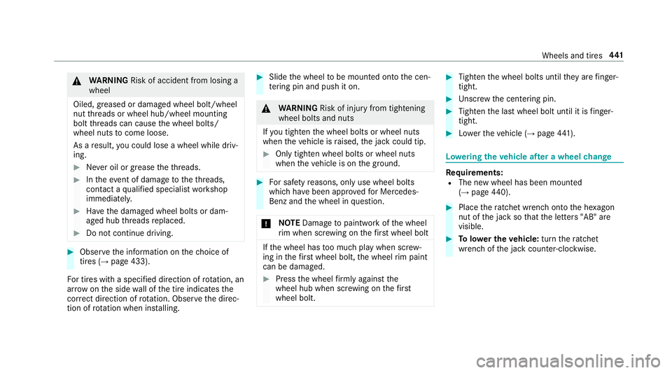
#Slide the wheel tobe mounted onto the cen‐
te ring pin and push it on.
&
WARNING Risk of injury from tightening
wheel bolts and nuts
If yo u tighten the wheel bolts or wheel nuts
when theve hicle is raised, the jack could tip.
#Only tighten wheel bolts or wheel nuts
when theve hicle is on the ground.
#Fo r saf etyre asons, only use wheel bolts
which ha vebeen appr ovedfo r Mercedes-
Benz and the wheel in question.
* NO
TEDama getopaintwork of the wheel
ri m when scr ewing on thefirs t wheel bolt
If th e wheel has too much play when scr ew‐
ing in thefirs t wheel bolt, the wheel rim paint
can be dama ged.
#Press the wheel firm lyagainst the
wheel hub when scr ewing on thefirs t
wheel bolt.
#Ti ghten the wheel bolts until they are finger-
tight.
#Un scr ew the centering pin.
#Tighten the last wheel bolt until it is finger-
tight.
#Lo we rth eve hicle (→page 441).
Lo weri ngtheve hicle af ter a wheel change
Re quirements:RThe new wheel has been mounted
(→page 440).
#Plac eth era tchet wrench onto the he xagon
nut of the jack so that the letters "AB" are
visible.
#To lowe r the vehicle: turnthera tchet
wrench of the jack counter-clockwise.
Wheels and tires 44
1
Page 452 of 562
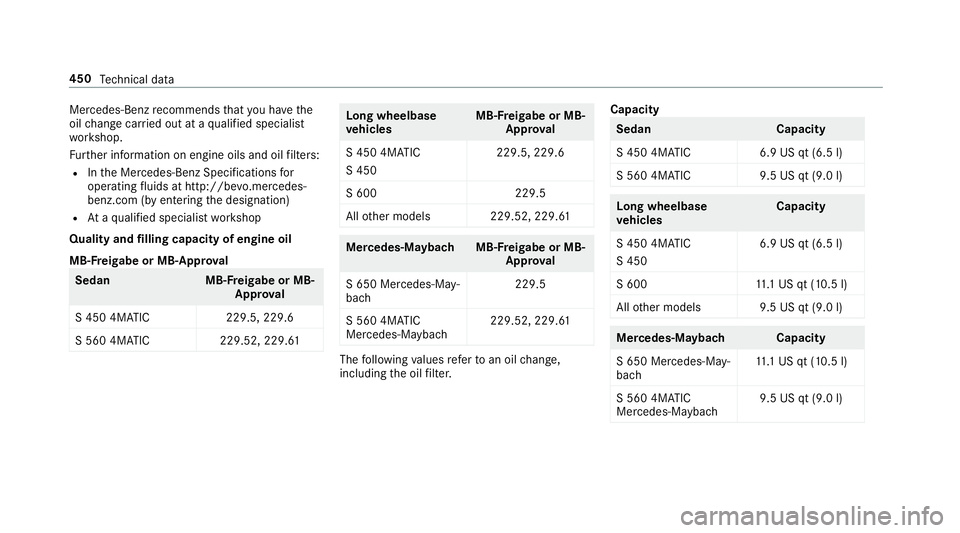
Mercedes-Benzrecommends that you ha vethe
oil change car ried out at a qualified specialist
wo rkshop.
Fu rther information on engine oils and oil filters:
RIn the Mercedes-Benz Specifications for
operating fluids at http:/ /bevo.mercedes-
benz.com (byen tering the designation)
RAt aqu alified specialist workshop
Quality and filling capacity of engine oil
MB- Freigabe or MB-A pproval
Sedan MB-Freigabe or MB-
Appr oval
S 450 4MATIC 229.5, 229.6
S 560 4MATIC 229.52, 229.61
Long wheelbase
vehicles MB-F
reigabe or MB-
Appr oval
S 450 4MATIC
S 450 229.5, 229.6
S 600 229.5
All other models 229.52, 229.61
Mercedes‑Maybac hMB-Freigabe or MB-
Appr oval
S 650 Mercedes-May‐
bach 229.5
S 560 4MATIC
Mercedes-Mayba ch229.52, 229.61
The
following values referto an oil change,
including the oil filter. Capacity
Seda
nC apacity
S 450 4MATIC 6.9 US qt (6.5 l)
S 560 4MATIC 9.5 US qt (9.0 l)
Long wheelbase
vehicles Capacity
S 450 4MATIC
S 450 6.9 US qt (6.5 l)
S 600 11.1 US qt (10.5 l)
All other models 9.5 US qt (9.0 l)
Mercedes‑Maybac hCapacity
S 650 Mercedes-May‐
bach 11
.1 US qt (10.5 l)
S 560 4MATIC
Mercedes-Maybach 9.5 US qt (9.0 l)
450
Tech nical da ta
Page 454 of 562

#Always use coolant appr ovedby
Mercedes-Benz.
#Obser vethe instructions in the
Mercedes-Benz Specifications for Oper‐
ating Fluids 310.1.
Ha ve the coolant regularly changed at a qualified
specialist workshop.
The proportion of cor rosion inhibitor/ antifreeze
concentrate in the engine cooling sy stem should
be:
RA minimum of 50% (antifreeze pr otection
down toappr oximately -35 °F (-37 °C)).
RA maximum of 55% (antifreeze pr otection
down to-49 °F (-45 °C)).
Coolant filling capacity
Seda nC apacity
S 450 4MATIC 13.9 US qt (13.2 l)
S 560 4MATIC 15.0 US qt (14.2 l)
Long wheelbase
vehicles Capacity
S 450 4MATIC
S 450 13
.9 US qt (13.2 l)
S 600 16.9 US qt (16.0 l)
All other models 15.0 US qt (14.2 l)
Mercedes‑Maybac hCapacity
S 650 Mercedes-May‐
bach 16
.9 US qt (16.0 l)
S 560 4MATIC
Mercedes-Maybach 15
.0 US qt (14.2 l)
Note s on windshield washer fluid
Obser vethe no tes on operating fluids
(→page 447).
&
WARNING ‑ Risk of fire and injury from
windshield washer concentrate
Wi ndshield washer concentrate is highly
fl ammable. It could ignite if it comes into
con tact wi thhot engine component parts or
th eex haust sy stem.
#Make sure that no windshield washer
concentrate spills out next tothefiller
opening.
* NO
TEBlocked spr aynozzles caused by
mixing windshield washer fluids
#Do not mix MB SummerFit and MB Win‐
te rFit with other windshield washer flu‐
ids.
Do not use distilled or de-ionized water asthefill
le ve l sensor may be triggered er roneously.
Re commended windshield washer fluid:
RAbo vefreezing point: e.g. MB SummerFit
RBelow freezing point: e.g. MB WinterFit
452
Tech nical da ta
Page 521 of 562

1,2, 3 ...
12 V sock et
see Soc ket (12 V)
11 5 V soc ket
see Soc ket (1 15 V)
360° camera ............................................ 224
Assigning as a favo rite ........................ 226
Ca re .................................................... 389
Fu nction .............................................. 224
Selecting a view .................................. 226
A
A/C function Activating/deactivating (multimedia
sy stem) ................................................ 158
Switching on/off (control panel) ......... 158
ABS (Anti-lock Braking Sy stem) ............ .189
Ac celeration
see Kickdown
Ac cess data
Editing ................................................ .333
Setting ................................................. 331 Ac
oustic locking verification signal
Ac tivating/deactivating ......................... 59
Ac tive Blind Spot Assi st......................... 238
Ac tivating/deactivating .......................2 40
Brake application ................................. 239
Fu nction .............................................. 238
Sy stem limitations .............................. .238
To wing a trailer .................................... 239
Ac tive Brake Assi st
Fu nction/no tes ................................... 192
Setting ................................................. 196
Ac tive Di stance Assist DI STRONIC........ 199
Ac tive Emergency Stop Assist .............2 07
Ac tive Lane Change Assi st.................. 206
Calling up a speed ............................... 200
Displa ysinthe Instrument Display ...... 208
Fu nction .............................................. 199
Increasing/decreasing speed ..............2 00
Re quirements ...................................... 200
Ro ute-based speed adjustment ...........203
St eering wheel buttons ............... .....
... 200
St oring a speed ................................... 200
Switching off/deactivating .................. 200
Switching on/activating ......................2 00
Sy stem limitations .............................. .199 Ac
tive Eme rgency Stop Assist ...............207
Ac tive hood (pedestrian pr otection) ......378
Me thod of operation ............................3 78
Re setting ............................................. 378
Ac tive Lane Change Assi st
Fu nction .............................................. 206
Switching on/off ................................. 207
Ac tive Lane Keeping Assist .................... 240
Fu nction .............................................. 240
Sensitivity (function/no tes) ................. 243
Setting the sensitivity .......................... 243
Switching on/off ................................. 242
Sy stem limitations .............................. .240
To wing a trailer .................................... 240
Ac tive Parking Assist .............................. 226
Cross Traf fic Alert ................................ 231
Drive AwayAssist ................................ 230
Exiting a pa rking space ...................... .229
Fu nction .............................................. 226
Pa rking ................................................ 228
Sy stem limitations .............................. .226
Ac tive Speed Limit Assi st.............. 202, 235
Di
splay ................................................ 202
Fu nction .............................................. 202
Index 51
9