2018 MERCEDES-BENZ GLS SUV drive program
[x] Cancel search: drive programPage 229 of 398
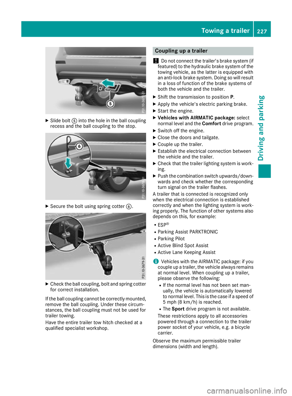
XSlide boltAinto the hole in the ball coupling
recess and the ball coupling to the stop.
XSecure the bolt using spring cotter B.
XCheck the ball coupling, bolt and spring cotter
for correct installation.
If the ball coupling cannot be correctly mounted,
remove the ball coupling. Under these circum-
stances, the ball coupling must not be used for
trailer towing.
Have the entire trailer tow hitch checked at a
qualified specialist workshop.
Coupling up a trailer
!
Do not connect the trailer's brake system (if
featured) to the hydraulic brake system of the
towing vehicle, as the latter is equipped with
an anti-lock brake system. Doing so will result
in a loss of function of the brake systems of
both the vehicle and the trailer.
XShift the transmission to position P.
XApply the vehicle's electric parking brake.
XStart the engine.
XVehicles with AIRMATIC package: select
normal level and the Comfortdrive program.
XSwitch off the engine.
XClose the doors and tailgate.
XCouple up the trailer.
XEstablish the electrical connection between
the vehicle and the trailer.
XCheck that the trailer lighting system is work-
ing.
XPush the combination switch upwards/down-
wards and check whether the corresponding
turn signal on the trailer flashes.
A trailer that is connected is recognized only
when the electrical connection is established
correctly and when the lighting system is work-
ing properly. The function of other systems also
depends on this, for example:
RESP®
RParking Assist PARKTRONIC
RParking Pilot
RActive Blind Spot Assist
RActive Lane Keeping Assist
iVehicles with the AIRMATIC package: if you
couple up a trailer, the vehicle always remains
at normal level. When coupling up a trailer,
please observe the foll
owing:
RIf the normal level has not been set man-
ually, the vehicle is automatically lowered
to normal level. This is the case if a speed of
5 mph (8 km/h) is reached.
RThe
Sport drive program is not available.
These restrictions apply to all accessories
powered through a connection to the trailer
power socket of your vehicle, e.g. a bicycle
carrier.
Observe the maximum permissible trailer
dimensions (width and length).
Towing a trailer227
Driving and parking
Z
Page 237 of 398
Left control panel
=
;RCalls up the menu and menu bar
9
:Press briefly:
RScrolls in lists
RSelects a submenu or function
RIn theAudiomenu: selects the
previous or next station, when the
preset list or station list is active,
or the previous or next audio track
or video scene
RIn the Tel(Telephone) menu:
switches to the phone book and
selects a name or telephone num-
ber
9
:Press and hold:
RIn the Audiomenu: selects a pre-
set list or a station list in the
desired frequency range or an
audio track or video scene using
rapid scrolling
RIn the Tel(Telephone) menu:
starts rapid scrolling if the phone
book is open
aRConfirms the selection or display
message
RIn the Tel(Telephone) menu:
switches to the phone book and
starts dialing the selected number
%Press briefly:
RBack
RSwitches off voice-operated con-
trol for navigation or the Voice
Control System
RHides display messages or calls up
the last Tripmenu function used
RExits the telephone book/redial
memory
%Press and hold:
RCalls up the standard display in the
Tripmenu
Right control panel
~RRejects or ends a call
RExits the telephone book/redial
memory
6RMakes or accepts a call
RSwitches to the redial memory
W
XRAdjusts the volume
8RMute
?RSwitches on voice-operated con-
trol for navigation or the Voice
Control System
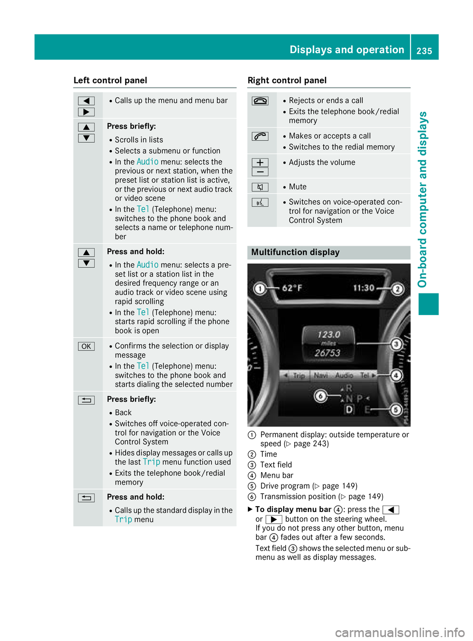
Multifunction display
:Permanent display: outside temperature or
speed (Ypage 243)
;Time
=Text field
?Menu bar
ADrive program (Ypage 149)
BTransmission position (Ypage 149)
XTo display menu bar ?: press the=
or ; button on the steering wheel.
If you do not press any other button, menu
bar ?fades out after a few seconds.
Text field =shows the selected menu or sub-
menu as well as display messages.
Displays and operation235
On-board computer and displays
Z
Page 243 of 398
XPress the6ora button to start dialing.
or
XTo exit the redial memory: press the~
or % button.
Assistance menu
Introduction
Depending on the equipment installed in the
vehicle, you have the following options in the
DriveAssist
menu:
RDisplaying the assistance graphic
(Ypage 241)
RActivating/deactivating the Traffic Sign
Assist display (Ypage 241)
RActivating or deactivating Steering Pilot
(Ypage 241)
RActivating or deactivating Active Brake Assist (Ypage 242)
RActivating or deactivating Active Brake Assist
with cross-traffic function (Ypage 242)
RActivating/deactivating ATTENTION ASSIST
(Ypage 242)
RActivating/deactivating Blind Spot Assist or
Active Blind Spot Assist (Ypage 242)
RActivating/deactivating Lane Keeping Assist
or Active Lane Keeping Assist (Ypage 242)
Displaying the assistance graphic
XPress the =or; button on the steering
wheel to select the DriveAssistmenu.
XPress9or: to select AssistanceGraphic.
XConfirm by pressing aon the steering
wheel.
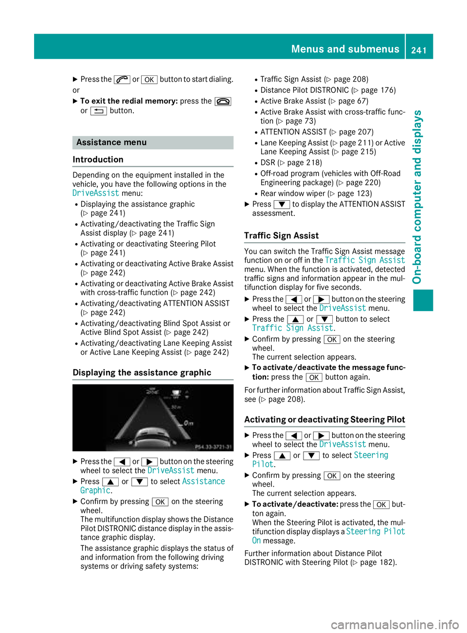
The multifunction display shows the Distance
Pilot DISTRONIC distance display in the assis-
tance graphic display.
The assistance graphic displays the status of
and information from the following driving
systems or driving safety systems:
RTraffic Sign Assist (Ypage 208)
RDistance Pilot DISTRONIC (Ypage 176)
RActive Brake Assist (Ypage 67)
RActive Brake Assist with cross-traffic func-
tion (Ypage 73)
RATTENTION ASSIST (Ypage 207)
RLane Keeping Assist (Ypage 211) or Active
Lane Keeping Assist (Ypage 215)
RDSR (Ypage 218)
ROff-road program (vehicles with Off-Road
Engineering package) (Ypage 220)
RRear window wiper (Ypage 123)
XPress :to display the ATTENTION ASSIST
assessment.
Traffic Sign Assist
You can switch the Traffic Sign Assist message
function on or off in the TrafficSignAssistmenu. When the function is activated, detected
traffic signs and information appear in the mul-
tifunction display for five seconds.
XPress the=or; button on the steering
wheel to select the DriveAssistmenu.
XPress the9or: button to select
Traffic Sign Assist.
XConfirm by pressing aon the steering
wheel.
The current selection appears.
XTo activate/deactivate the message func-
tion: press the abutton again.
For further information about Traffic Sign Assist,
see (
Ypage 208).
Activating or deactivating Steering Pilot
XPress the =or; button on the steering
wheel to select the DriveAssistmenu.
XPress9or: to select SteeringPilot.
XConfirm by pressing aon the steering
wheel.
The current selection appears.
XTo activate/deactivate: press theabut-
ton again.
When the Steering Pilot is activated, the mul- tifunction display displays a Steering
PilotOnmessage.
Further information about Distance Pilot
DISTRONIC with Steering Pilot (
Ypage 182).
Menus and submenus241
On-board computer and displays
Z
Page 247 of 398
For further information on belt adjustment, see
(Ypage 48).
Switching the fold-in mirrors when lock-
ing feature on/off
This function is only available when the vehicle is
equipped with the electrical fold-in function.
When you activate theAuto.
MirrorFoldingfunction, the exterior mirrors are folded in when
the vehicle is locked. The exterior mirrors fold
out automatically again as soon as you unlock
the vehicle.
XPress the =or; button on the steering
wheel to select the Sett.menu.
XPress the:or9 button to select the
Conveniencesubmenu.
XPress ato confirm.
XPress the :or9 button to select the
Auto. Mirror Foldingfunction.
If the Auto. Mirror Foldingfunction is
switched on, the multifunction display shows
the exterior mirror in orange.
XPress the abutton to save the setting.
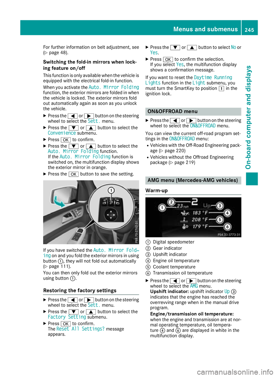
If you have switched the Auto. Mirror Fold‐ingon and you fold the exterior mirrors in using
button :, they will not fold out automatically
(
Ypage 111).
You can then only fold out the exterior mirrors
using button :.
Restoring the factory settings
XPress the=or; button on the steering
wheel to select the Sett.menu.
XPress the:or9 button to select the
Factory Settingsubmenu.
XPress ato confirm.
The Reset All Settings?message
appears.
XPress the :or9 button to select Noor
Yes.
XPress ato confirm the selection.
If you select Yes, the multifunction display
shows a confirmation message.
If you want to reset the Daytime Running
Lightsfunction in theLightsubmenu, you
must turn the SmartKey to position 1in the
ignition lock.
ON&OFFROAD menu
XPress the =or; button on the steering
wheel to select the ON&OFFROADmenu.
You can view the current off-road program set-
tings in the ON&OFFROAD
menu:
RVehicles with the Off-Road Engineering pack-
age (Ypage 220)
RVehicles without the Offroad Engineering
package (Ypage 219)
AMG menu (Mercedes-AMG vehicles)
Warm-up
:Digital speedometer
;Gear indicator
=Upshift indicator
?Engine oil temperature
ACoolant temperature
BTransmission oil temperature
XPress the =or; button on the steering
wheel to select the AMGmenu.
Upshift indicator: upshift indicatorUp=
indicates that the engine has reached the
overrevving range when in the manual drive
program.
Engine/transmission oil temperature:
when the engine and transmission are at nor-
mal operating temperature, oil tempera-
ture ?and Bare displayed in white in the
multifunction display.
Menus and submenus245
On-board computer and displays
Z
Page 323 of 398
The data you receive contains the following
information:
Rthe location where the speed limit was excee-
ded
Rthe time at which the speed limit was excee-
ded
Rthe selected speed limit which was exceeded
Geo fencing
Geo fencing allows you to select areas which the
vehicle should not enter or leave. You will be
informed if the vehicle crosses the boundaries
of the selected areas. You can select the way in
which you receive this information beforehand.
Possible options include text message, e-mail or an automated call.
The area can be determined as either a circle or
a polygon with a maximum of ten corners. You
can specify up to ten areas simultaneously. Dif-
ferent settings are possible for each area.
These settings can be called up under "Owners
Online" at http://www.mbusa.com.
Alternatively, you can also trigger an Info call
and notify the customer service representative
that you wish to activate geo-fencing.
Currently inactive areas can be activated by text
message.
Triggering the vehicle alarm
With this function, you can trigger the vehicle's
panic alarm via text message. An alarm sounds
and the exterior lighting flashes. Depending on
the setting, the panic alarm lasts five or ten sec-
onds. Afterwards, the alarm switches off.
Garage door opener
General notes
The HomeLink®garage door opener integrated
in the rear-view mirror allows you to operate up to three different door and gate systems.
Use the integrated garage door opener only on
garage doors that:
Rhave safety stop and reverse features and
Rmeet current U.S. federal safety standards
Once programed, the integrated garage door
opener in the rear-view mirror will assume the
function of the garage door system's remote control. Please also read the operating instruc-
tions for the garage door system.
When programming a garage door opener, park
the vehicle outside the garage. Do not run the
engine while programming.
Certain garage door drives are incompatible
with the integrated garage door opener. If you
have difficulty programing the integrated garage
door opener, contact a Mercedes-Benz Service
Center.
Alternatively, you can call the following tele-
phone assistance services:
RUSA: Mercedes-Benz Customer Assistance
Center at 1-800 FOR-MERCEDES
RCanada: Customer Service at
1-800-387-0100
RHomeLink®hotline 1-800-355-3515 (free of
charge)
More information on HomeLink
®and/or com-
patible products is also available online at
http://www.homelink.com.
Notes on the declaration of conformity
(
Ypage 30).
USA: FCC ID: CB2HMIHL4
Canada: IC: 279B-HMIHL4
Important safety notes
GWARNING
When you operate or program the garage door
with the integrated garage door opener, per-
sons in the range of movement of the garage
door can become trapped or struck by the
garage door. There is a risk of injury.
When using the integrated garage door
opener, always make sure that nobody is
within the range of movement of the garage
door.
GWARNING
Combustion engines emit poisonous exhaust
gases such as carbon monoxide. Inhaling
these exhaust gases leads to poisoning. There
is a risk of fatal injury. Therefore never leave
the engine running in enclosed spaces with-
out sufficient ventilation.
Features321
Stowage and features
Z
Page 324 of 398

Programming
Programming the buttons
Pay attention to the "Important safety notes"
(Ypage 321).
Garage door remote controlAis not included
with the integrated garage door opener.
XTurn the SmartKey to position 2in the igni-
tion lock (Ypage 140).
XSelect one of buttons ;to? to use to con-
trol the garage door drive.
XTo start programming mode: press and
hold one of buttons ;to? on the integrated
garage door opener.
The garage door opener is now in program-
ming mode. After a short time, indicator
lamp :lights up yellow.
Indicator lamp :lights up yellow as soon as
button ;,=or? is stored for the first time.
If the selected button has already been pro-
gramed, indicator lamp :will only light up
yellow after ten seconds have elapsed.
XRelease button ;,=or?. Indicator
lamp :flashes yellow.
XTo program the remote control: point
garage door remote control Atowards but-
tons ;to? on the rear-view mirror at a dis-
tance of 2 to 8 in (5 to 20 cm).
XPress and hold button Bon remote control
A until indicator lamp :lights up green.
When indicator lamp :lights up green: pro-
gramming is finished.
When indicator lamp :flashes green: pro-
gramming was successful. The next step is to synchronize the rolling code (
Ypage 322).
XRelease button Bon remote control Afor
the garage door drive system.
If indicator lamp :lights up red: repeat the
programing procedure for the corresponding
button on the rear-view mirror. When doing so, vary the distance between remote control
A
and the rear-view mirror.
The required distance between remote con-
trol Aand the integrated garage door opener
depends on the garage door drive system.
Several attempts might be necessary. You
should test every position for at least
25 seconds before trying another position.
Synchronizing the rolling code
Pay attention to the "Important safety notes"
(Ypage 321).
If the garage door system uses a rolling code,
you will also have to synchronize the garage
door system with the integrated garage door
opener in the rear-view mirror. To do this you will
need to use the programming button on the door
drive control panel. The programming button
may be located in different places depending on
the manufact
urer. It is usually located on the
door drive unit on the garage ceiling.
Familiarize yourself with the garage door drive
operating instructions, e.g. under "Program-
ming additional remote controls", before carry-
ing out the following steps.
Your vehicle must be within reach of the garage
door or gate opener drive. Make sure that nei-
ther your vehicle nor any persons/objects are
present within the sweep of the door or gate.
XTurn the SmartKey to position 2in the igni-
tion lock (Ypage 140).
XGet out of the vehicle.
XPress the programming button on the door
drive unit.
You now have 30 seconds to initiate the next
step.
XGet into the vehicle.
XPress previously programed button ;,=
or ? on the integrated garage door opener
repeatedly until the door closes.
The rolling code synchronization is then com- plete.
Notes on programming the remote con-
trol
Canadian radio frequency laws require a "break"(or interruption) of the transmission signals
after broadcasting for a few seconds. Therefore,
these signals may not last long enough for the
integrated garage door opener. The signal is not recognized during programming. Comparable
322Features
Stowage and features
Page 325 of 398
with Canadian law, some U.S. garage door open-
ers also feature a "break".
Proceed as follows:
Rif you live in Canada.
Rif you have difficulties programming the
garage door opener (regardless of where youlive) when following the programming steps.
XPress and hold one of buttons ;to? on the
integrated garage door opener.
After a short time, indicator lamp :lights up
yellow.
XRelease the button.
Indicator lamp :flashes yellow.
XPress button Bof garage door remote con-
trol Afor two seconds, then release it for two
seconds.
XPress button Bagain for two seconds.
XRepeat this sequence on button Bof remote
control Auntil indicator lamp :lights up
green.
When indicator lamp :lights up green: pro-
gramming is finished.
When indicator lamp :flashes green: pro-
gramming was successful. The next step is to
synchronize the rolling code.
XRelease button Bof remote control Aof the
garage door drive.
When indicator lamp :lights up red: repeat
the programming process for the correspond-
ing button on the rear-view mirror. When
doing so, vary the distance between remote
control Aand the rear-view mirror.
The required distance between remote con-
trol Aand the integrated garage door opener
depends on the garage door drive system.
Several attempts might be necessary. You
should test every position for at least
25 seconds before trying another position.
Problems when programming
If you are experiencing problems programming
t
he integrated garage door opener on the rear-
view mirror, take note of the following instruc-
tions:
RCheck the transmitter frequency used by
garage door drive remote control Aand
whether it is supported. The transmitter fre-
quency can usually be found on the back of
remote control Afor the garage door drive.
The integrated garage door opener is com-
patible with devices that have units which operate in the frequency range of 280 to
433 MHz.
RReplace the batteries in garage door remote
control
A. This increases the likelihood that
garage door remote control Awill transmit a
strong and precise signal to the integrated
garage door opener.
RWhen programming, hold remote control A
at varying distances and angles from but-
tons ;to? which you are programming. Try
various angles at a distance between 2and
8 inches (5to 20 cm) or at the same angle but
at varying distances.
RIf a further remote control Ais available for
the same garage door drive, repeat the same
programming steps with this remote control
A. Before performing these steps, make sure
that new batteries have been installed in
garage door drive remote control A.
RNote that some remote controls only transmit
for a limited amount of time (the indicator
lamp on the remote control goes out). Press
buttonBon remote control Aagain before
transmission ends.
RAlign the antenna cable of the garage door
opener unit. This can improve signal recep-
tion/transmission.
Opening/closing the garage door
After it has been programmed, the integrated
garage door opener performs the function of the
garage door system remote control. Please also
read the operating instructions for the garage
door system.
XTurn the SmartKey to position 2in the igni-
tion lock (Ypage 140).
XPress button ;,=or? which you pro-
grammed to operate the garage door.
Garage door system with a fixed code: indi-
cator lamp :lights up green.
Garage door system with a rolling code: indi-
cator lamp :flashes green.
The transmitter will transmit a signal as long
as the button is pressed. The transmission is
halted after a maximum of ten seconds and
indicator lamp :lights up yellow.
XPress button ;,=or? again if necessary.
Features323
Stowage and features
Z
Page 346 of 398
Battery (vehicle)
12 V battery - important safety notes
Special tools and expert knowledge are required
when working on the battery, e.g. removal and
installation. You should therefore have all work
involving the battery carried out at a qualified
specialist workshop.
GWARNING
Work carried out incorrectly on the battery
can lead, for example, to a short circuit and
thus damage the vehicle electronics. This can
lead to function restrictions applying to
safety-relevant systems, e.g. the lighting sys-
tem, the ABS (anti-lock braking system) or the
ESP
®(Electronic Stability Program). The oper-
ating safety of your vehicle may be restricted.
You could lose control of the vehicle, for
example:
Rwhen braking
Rin the event of abrupt steering maneuvers
and/or when the vehicle's speed is not
adapted to the road conditions
There is a risk of an accident.
In the event of a short circuit or a similar inci-
dent, contact a qualified specialist workshop
immediately. Do not drive any further. You
should have all work involving the battery car- ried out at a qualified specialist workshop.
For further information about ABS and ESP
®,
see (Ypage 66) and (Ypage 69).
GWARNING
Electrostatic build-up can lead to the creation of sparks, which could ignite the highly explo-
sive gases of a battery. There is a risk of an
explosion.
Before handling the battery, touch the vehicle
body to remove any existing electrostatic
build-up.
The highly flammable gas mixture forms when
charging the battery as well as when jump-start-
ing. Always make sure that neither you nor the bat-
tery is electrostatically charged. A build-up of
electrostatic charge can be caused, for exam-
ple:
Rby wearing clothing made from synthetic
fibers
Rdue to friction between clothing and seats
Rif you push or pull the battery across the car-
pet or other synthetic materials
Rif you wipe the battery with a cloth
GWARNING
During the charging process, a battery produ-
ces hydrogen gas. If a short circuit occurs or
sparks are created, the hydrogen gas can
ignite. There is a risk of an explosion.
RMake sure that the positive terminal of a
connected battery does not come into con- tact with vehicle parts.
RNever place metal objects or tools on a bat-
tery.
RIt is important that you observe the descri-
bed order of the battery terminals when
connecting and disconnecting a battery.
RWhen jump-starting, make sure that the
battery poles with identical polarity are
connected.
RIt is particularly important to observe the
described order when connecting and dis-
connecting the jumper cables.
RNever connect or disconnect the battery
terminals while the engine is running.
GWARNING
Battery acid is caustic. There is a risk of injury.
Avoid contact with skin, eyes or clothing. Do
not inhale any battery gases. Do not lean over
the battery. Keep children away from batter-
ies. Wash away battery acid immediately with
plenty of clean water and seek medical atten-
tion.
HEnvironmental note
Batteries contain dangerous
substances. It is against the
law to dispose of them with
344Battery (vehicle)
Breakdo wn assis tance