2018 MERCEDES-BENZ GLS SUV warning
[x] Cancel search: warningPage 228 of 398
RMaintain a greater distance from the vehicle
in front than when driving without a trailer.
RAvoid braking abruptly. If possible, brake gen-tly at first to allow the trailer to run on. Then,
increase the braking force rapidly.
RThe values given for gradient-climbing capa-
bilities from a standstill refer to sea level.
When driving in mountainous areas, note that
the power output of the engine and, conse-
quently, the vehicle's gradient-climbing capa-
bility, decreases with increasing altitude.
Installing the ball coupling
GWARNING
If the ball coupling is not correctly installed
and secured, it can come loose during the
journey and endanger other road users. There is a risk of an accident and injury.
Always install and secure the ball coupling as
described. Before every journey, ensure that
the ball coupling is secured with the bolt and
the corresponding spring cotter.
GWARNING
If the ball coupling is not installed correctly or not secured with the bolt provided and the
corresponding spring cotter, the trailer may
come loose. There is a risk of an accident.
Always install and secure the ball coupling as
described. Before every journey, ensure that
the ball coupling is secured with the bolt and
the corresponding spring cotter.
GWARNING
If the ball coupling is not installed and secured
correctly the trailer may come loose. There is
a risk of an accident.
Install and secure the ball coupling as descri-
bed in the ball coupling installation instruc-
tions. Make sure that the ball coupling is
installed and secured correctly before every
journey.
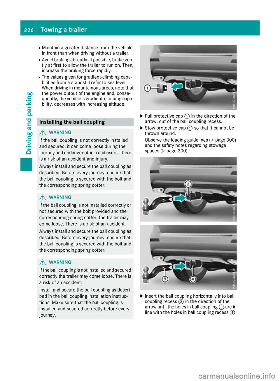
XPull protective cap :in the direction of the
arrow, out of the ball coupling recess.
XStow protective cap :so that it cannot be
thrown around.
Observe the loading guidelines (
Ypage 300)
and the safety notes regarding stowage
spaces (
Ypage 300).
XInsert the ball coupling horizontally into ball
coupling recess ;in the direction of the
arrow until the holes in ball coupling =are in
line with the holes in ball coupling recess ?.
226Towing a trailer
Driving and parking
Page 231 of 398
Decouplingatrailer
GWARNING
If you uncoupl e atrailer wit hth eoverrun
brake engaged, you could trap your han d
between th evehicle and th etrailer drawbar .
There is aris kof injury.
Do no tuncoupl e atrailer if th eoverrun brake
is engaged.
GWARNING
Vehicles wit hlevel control:
The vehicle is lowered as soo nas you discon-
nect th etrailer cable. Thi scould result in your
limbs or those of other people that are
between th evehicle bod yand tires or under-
neat hth evehicle bein gtrapped. There is a
ris kof injury.
Mak esur ethat nobod yis in th eimmediate
vicinit yof th ewhee lhousings or under th e
vehicle when you disconnec tth etrailer cable.
!Do no tdisconnec t atrailer wit han engage d
overrun brake .Otherwise ,your vehicle could
be damaged by th ereboundin gof th eoverrun
brake .
XShift th etransmissio nto position P.
XApply thevehicle' selectric parking brake .
XStart theengine.
XClos eth edoors and tailgate.
XApply th etrailer's parking brake .
XDetach thetrailer cable and decoupl eth e
trailer .
XSwitchof fth eengine.
Permissible trailer loads an ddrawbar
loads
Weight specifications
Maximum allowable gross mass
The gross vehicle weight of th etrailer is calcu-
lated by addin gth eweight of th etrailer to th e
weight of th eload and equipmen ton th etrailer .
You will fin dinstallin gdimensions and load s
under "Technical data" (
Ypage 395).
Permissible noseweigh t
You will findinstallin gdimensions and load s
under "Technical data" (Ypage 395).
Loadingatrailer
RWhe nloadin gth etrailer ,mak esur ethat nei-
ther th epermissible gross weight of th etrailer
no rth egross vehicle weight are exceeded.
The permissible gross vehicle weight is indi-
cated on th eidentification plat elocated on
th eB-pilla ron th edriver's sid eof th evehicle.
You can fin dth emaximum permissible values
on th etyp eplates of your vehicle and th e
trailer .Whe ncalculatin ghow muc hweight
th evehicle and trailer may carry, pay atten-
tion to th erespective lowest values.
RThe trailer drawbar load on th eball couplin g
mus tbe adde dto th erea raxl eload to avoid
exceedin gth epermissible gross axl eweight .
The permissible gross vehicle weight is indi-
cated on th eidentification plat elocated on
th eB-pilla ron th edriver's sid eof th evehicle.
iMercedes-Ben zrecommends atrailer load
wher eth etrailer drawbar noseweigh t
accounts fo r 8 %to 15 %of th etrailer's per -
missible gross weight .
iThe weight of additional accessories ,pas-
sengers, and cargo reduce sth epermissible
trailer load and drawbar load fo ryour vehicle.
Checking th evehicle an dtrailer weigh t
RTo checkthat th eweight sof th etowin gvehi-
cl e and th etrailer compl ywit hth emaximum
permissible values, hav eth evehicle/trailer
combination (includin gth edriver ,passen -
gers, and cargo wit h afullylade ntrailer )
weighed on acalibrated weighbridge .
RCheckth egross axl eweight ratin gof th efron t
and rea raxles, th egross weight of th etrailer
and th etrailer drawbar noseweight.
Removin gth eball coupling
XRemov eth esprin gcotter.
XRemov eth ebolt from th eball couplin g
recess .
XRemov eth eball couplin gfrom th eball cou-
plin grecess .
Towing a trailer229
Driving and parking
Z
Page 232 of 398
XClean theballcouplin gif it is dirt y.
XStow the ballcouplin g so that itcannot be
thrown aroun d.
Observe the loading guidelines (
Ypage 300)
and the safety notes regarding stowage spaces
(
Ypage 300).
In formation on cleaning and care of the trailer
tow hitch (
Ypage 335).
Trailer power supply
!
Accessories with a maximum power con-
sumption of 180 W can beconnected to the
permanent power supply.
You must not charge a trailer battery using the
power supply.
The trailer socket of your veh icle is equipped at
the factory with a permanent power supply.
The permanent power supply is supplied via
trailer socket pin4.
The trailer's permanent power supply is
swit ched off inthe event of low veh icle supply
voltage and after six hours at the latest.
A qualif ied specialist workshop can provide
more information about installing the trailer
electrics.
Bicycle rack
General notes
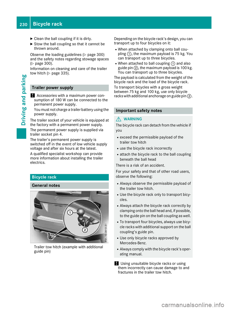
Trailer tow hitch (example withaddit ional
guide pin) Depending on the bicycle rack's design, you can
transport up to four bicycles on it:
RWhen attached by clamping onto ball cou-
pling
:, the maximum payload is 75 kg. You
can transport up to three bicycles.
RWhen attached to ball coupling :and also
guide pin ;, the maximum payload is 100 kg.
You can transport up to three bicycles.
The payload iscalculated from the weight of the
bic ycle rack and the load of the bicycle rack.
To transport bicycles with a gross weight
between 75 kg and 100 kg, use only bicycle
racks with additional anchorage on guide pin ;.
Important safety notes
GWARNING
The bicycle rack can detach from the vehicle if
you
Rexceed the permissible payload of the
trailer tow hitch
Ruse the bicycle rack incorrectly
Rattach the bicycle rack to the ball coupling
beneath the ball head
There is a risk of an accident.
For your safety and that of other road users,
observe the foll owing:
RAlwa ys observe the permissible payload of
the trailer tow hitch.
RUse the bicycle rack only to transport bicy-
cles.
RAlways attach the bicycle rack correctly by
clamping onto the ball head and, if possible,
to the guide pin on the ball coupling as well.
RTo transport four bicycles, always use bicy-
cle racks with additional support on the ball
coupling's guide pin.
RUse only bicycle racks approved by
Mercedes-Benz.
RAlwa ys comply with the bicycle rack's oper-
ating manual.
!Using unsuitab lebicycle racks or using
them incorrectly can cause damage to and
fractures in the trailer tow hitch.
230Bicycle rack
Driving and parking
Page 235 of 398
Important safety notes
GWARNING
If you operate information systems and com-
munication equipmen tintegrate din th evehi-
cle when driving ,you may be distracte dfrom
th etraffic situation .You could also lose con-
trol of th evehicle. Ther eis aris kof an acci-
dent.
Only operate this equipmen twhen th etraffic
situation permits. If you are no tsur ethat this
is possible ,park th evehicl epayin gattention
to traffic condition sand operate th eequip-
men twhen th evehicl eis stationary.
You must observ eth elegal requirements for th e
country in whic hyou are currentl ydriving when
operating th eon-board computer.
GWARNIN G
If th einstrumen tcluste rhas faile dor mal-
functioned, you may no trecognize function
restriction sin systems relevan tto safety. The
operating safet yof your vehicl emay be
impaired .Ther eis aris kof an accident.
Drive on carefully. Hav eth evehicl echecke d
at aqualified specialist workshop immedi-
ately.
If th eoperating safet yof your vehicl eis
impaired ,pull ove ras soo nas it is saf eto do so.
Contac t aqualified specialist workshop.
The on-board computer only shows message sor
warning sfrom certain systems in th emultifunc-
tion display. You should therefor emak esur e
your vehicl eis operating safely at all times .
Fo ran overview, see th einstrumen tpanel illus-
tration (
Ypage 37).
Displays and operation
Instrument cluster lighting
The lighting in th einstrumen tcluster, in th edis-
plays and th econtrol sin th evehicl einterior can
be adjusted usin gth ebrightness control knob.
The brightness control knob is locate don th e
botto mleftof th einstrumen tcluste r
(
Ypage 37).
XTurn th ebrightness control knob clockwise or
counter-clockwise.
If you tur nth eligh tswitch to Ã,Tor
L, thebrightness is dependen tupon th e
brightness of th eambien tlight.
iThe ligh tsensor in th einstrumen tcluste r
automatically control sth ebrightness of th e
multifunction display.
In daylight, th edisplays in th einstrumen t
cluste rare no tilluminated.
Speedometer with segments
The segments in th espeedometer indicat e
whic hspee drange is available.
RCruis econtrol activated (Ypage 174):
The segments ligh tup from th estore dspee d
to th emaximum speed.
RDistanc ePilot DISTRONI Cis activated
(Ypage 176):
On eor two segments in th eset spee drange
ligh tup.
RDistanc ePilot DISTRONI Cdetects avehicl ein
fron tmoving mor eslowly than th estore d
speed:
The segments between th espee dof th evehi-
cle in fron tand th estore dspee dligh tup.
Tachometer
!
Do no tdriv ein th eoverrevving range, as this
could damag eth eengine.
The red ban din th etachometer indicates th e
engine's overrevving range.
The fuel suppl yis interrupted to protect th e
engin ewhen th ered ban dis reached.
Outside temperature display
You should pay special attention to road condi-
tion swhen temperatures are aroun dfreezing
point.
Bea rin min dthat th eoutside temperature dis-
play indicates th etemperature measured and
does no trecord th eroad temperature.
The outside temperature display is in th emulti-
function display (
Ypage 235).
Displays and operation233
On-board computer and displays
Z
Page 236 of 398
There is a short delay before a change in outside
temperature appears in the multifunction dis-
play.
Coolant temperature gauge
GWARNING
Opening the hood when the engine is over-
heated or when there is a fire in the engine
compartment could expose you to hot gases
or other service products. There is a risk of
injury.
Let an overheated engine cool down before
opening the hood. If there is a fire in the
engine compartment, keep the hood closed
and contact the fire department.
!If the coolant temperature is too high, a dis-
play message is shown.
If the coolant temperature display is in the
area marked in red, do not continue driving.
Otherwise, the engine will be damaged.
The coolant temperature gauge is in the instru-
ment cluster on the right-hand side (
Ypage 37).
Under normal operating conditions and with the
specified coolant level, the coolant temperature gauge may rise to the red marking.
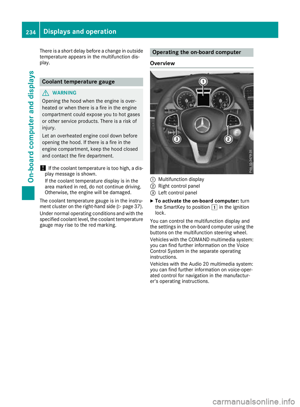
Operating the on-board computer
Overview
:Multifunction display
;Right control panel
=Left control panel
XTo activate the on-board computer: turn
the SmartKey to position 1in the ignition
lock.
You can control the multifunction display and
the settings in the on-board computer using the
buttons on the multifunction steering wheel.
Vehicles with the COMAND multimedia system: you can find further information on the Voice
Control System in the separate operating
instructions.
Vehicles with the Audio 20 multimedia system:
you can find further information on voice-oper-
ated control for navigation in the manufactur-
er's operating instructions.
234Displays and operation
On-board computer and displays
Page 242 of 398
Telephone menu
Introduction
GWARNING
If you operate information systems and com-
munication equipment integrated in the vehi-
cle when driving, you may be distracted from
the traffic situation. You could also lose con-
trol of the vehicle. There is a risk of an acci-
dent.
Only operate this equipment when the traffic
situation permits. If you are not sure that this
is possible, park the vehicle paying attention
to traffic conditions and operate the equip-
ment when the vehicle is stationary.
When telephoning, you must observe the legal
requirements for the country in which you are
currently driving.
XSwitch on the mobile phone (see the manu-
facturer’s operating instructions).
XSwitch on the multimedia system (see the
Digital Operator's Manual)
XEstablish a Bluetooth®connection to the mul-
timedia system (see the Digital Operator's
Manual).
XPress the =or; button on the steering
wheel to select the Telmenu.
You will see one of the following display mes-
sages in the multifunction display:
RPhone READYor the name of the network
provider: the mobile phone has found a net-
work and is ready to receive.
RPhone No Service: there is no network
available or the mobile phone is searching for
a network.
Accepts a call
If someone calls you when you are in the Telmenu, a display message appears in the multi-
function display.
You can accept a call at any time regardless of
the menu selected.
XPress the6button on the steering wheel
to accept an incoming call.
Rejecting or ending a call
You can end or reject a call even if you are not in
the Telmenu.
XPress the ~button on the steering wheel
to reject or end a call.
Selecting an entry from the phone book
XPress the =or; button on the steering
wheel to select the Telmenu.
XPress the9,:ora button to
switch to the phone book.
XAuthorize access to the phone book on the
phone.
XPress the 9or: button to select the
desired name.
or
XTo start rapid scrolling: press and hold the
9 or: button for longer than one sec-
ond.
Rapid scrolling stops when you release the
button or reach the end of the list.
XIf only one telephone number is stored for
a name: press the 6ora button to
start dialing.
or
XIf there is more than one number for a
particular name: press the6ora
button to display the numbers.
XPress the 9or: button to select the
number you want to dial.
XPress the 6ora button to start dialing.
or
XTo exit the telephone book: press the~
or % button.
Redialing
The on-board computer saves the last names or
numbers dialed in the redial memory.
XPress the =or; button on the steering
wheel to select the Telmenu.
XPress the6button to switch to the redial
memory.
XPress the 9or: button to select the
desired name or number.
240Menus and submenus
On-board computer and displays
Page 244 of 398
Activating/deactivating Active Brake
Assist
You can use these functionsto activate/deac -
tivat eActive Brake Assis tor, on vehicles wit h
th eDrivin gAssistance package, to activat eor
deactivat eActive Brake Assis twit hcross-traffic
function .
XPress the= or; buttonon th esteering
whee lto select th eDriveAssistmenu.
XPress th e9 or: buttonto select
Brake Assist.
XPress ato confirm .
The curren tselection appears.
XTo activate/deactivate: press thea but-
to nagain .
When Active Brake Assis tor Active Brake
Assis twit hcross-traffic function is deactiva-
ted, th eæ symbol appear sin th emulti-
function display in th eassistanc egraphic dis-
play.
Further information on Active Brake Assis t
(
Ypage 67) and Active Brake Assis twit hcross -
traffic function (Ypage 72).
Activating/deactivating ATTENTION
ASSIST
XPress the= or; buttonon th esteering
whee lto select th eDriveAssistmenu.
XPress th e9 or: buttonto select
Attention Assist.
XPress th ea button.
The curren tselection appears.
XPress ato confirm .
XPress the: or9 buttonto set Off,
Standardor Sensitive.
XPress th ea buttonto sav eth esetting .
When ATTENTION ASSIST is deactivated, th e
é symbol appear sin th emultifunction dis-
play in th eassistanc egraphic sdisplay.
Fo rfurther information about ATTENTION
ASSIST ,see (
Ypage 207).
Activating/deactivating Blind Spot
Assist
XPress th e= or; buttonon th esteering
whee lto select th eDriveAssistmenu.
XPress th e9 or: buttonto select
Blind Spo tAssist.
XConfir mby pressing aon thesteering
wheel.
The curren tselection appears.
XTo activate/deactivate: press thea but-
to nagain .
Fo rfurther information about Blind Spot Assist,
see (
Ypage 209).
Fo rfurther information about Active Blind Spot
Assist, see (
Ypage 213).
Activating/deactivating Lane Keeping
Assist
XPress th e= or; buttonon th esteering
whee lto select th eDriveAssistmenu.
XPress th e9 or: buttonto select
Lan eKeepin gAssist.
XPress ato confirm .
The curren tselection appears.
XPress ato confirm .
XPress the: or9 buttonto set Off,
Standardor Adaptive.
When Lan eKeepin gAssis tor Active Lan e
Keepin gAssis tis activated, th emultifunction
display shows th elan emarking sas bright
lines in th eassistanc egraphic .
XPress th ea buttonto sav eth esetting .
Fo rfurther information about Lan eKeepin g
Assist, see (
Ypage 211).
Fo rfurther information about Active Lan eKeep-
ing Assist, see (
Ypage 215).
Service menu
Dependingon th eequipmen tinstalled in th e
vehicle, you hav eth efollowin goption sin th e
Serv.
menu:
Rcalling up display message sin message mem -
ory (Ypage 248)
Rrestarting th etire pressur eloss warning sys-
te m (Ypage 361) or checking th etire pres-
sur eelectronically (Ypage 363)
Rcalling up theservic edue dat e (Ypage 329).
242Menus and submenus
On-board computer and displays
Page 246 of 398
RHighway mode
RActive light function
RCornering light function
RExtended range fog lamps
ROff-road lights
Further information on the Intelligent Light Sys-
tem (
Ypage 117).
Vehicle submenu
Activating/deactivating the automatic
door locking mechanism
If you activate the AutomaticDoorLockfunc-
tion, the vehicle is centrally locked above a
speed of approximately 9 mph (15 km/h).
XPress the =or; button on the steering
wheel to select the Sett.menu.
XPress the:or9 button to select the
Vehiclesubmenu.
XPress ato confirm.
XPress the :or9 button to select the
Automatic Door Lockfunction.
When the Automatic Door Lockfunction is
activated, the vehicle doors are displayed in
orange in the multifunction display.
XPress the abutton to save the setting.
For further information on the automatic locking
feature, see (
Ypage 84).
Activating/deactivating the acoustic
locking verification signal
If you switch on the AcousticLockfunction, an
acoustic signal sounds when you lock the vehi-
cle.
XPress the =or; button on the steering
wheel to select the Settingsmenu.
XPress the:or9 button to select the
Vehiclesubmenu.
XPress ato confirm.
XPress the :or9 button to select the
Acoustic Lockfunction.
If the Acoustic Lockfunction is activated,
the & symbol in the multifunction display
lights up orange.
XPress the abutton to save the setting.
Convenience submenu
Activating/deactivating the EASY-
ENTRY/EXIT feature
GWARNING
When the EASY-ENTRY/EXIT feature adjusts
the steering wheel, you and other vehicle
occupants – particularly children – could
become trapped. There is a risk of injury.
While the EASY-ENTRY/EXIT feature is mak-
ing adjustments, make sure that no one has
any body parts in the sweep of the steering
wheel.
If somebody becomes trapped:
Rpress one of the memory function position
buttons, or
Rmove the switch for steering wheel adjust-
ment in the opposite direction to that in
which the steering wheel is moving.
The adjustment process is stopped.
XPress the =or; button on the steering
wheel to select the Sett.menu.
XPress the:or9 button to select the
Conveniencesubmenu.
XPress ato confirm.
XUsing :or9, select the EasyEntry/Exitfunction.
If the EasyEntry/Exitfunction is activated,
the vehicle steering wheel is displayed in
orange in the multifunction display.
XPress the abutton to save the setting.
Further information on the EASY-ENTRY/EXIT
feature (
Ypage 109).
Switching the seat belt adjustment on/off
XPress the =or; button on the steering
wheel to select the Settingsmenu.
XPress the:or9 button to select the
Conveniencesubmenu.
XPress ato confirm.
XPress the :or9 button to select the
Belt Adjustmentfunction.
If the BeltAdjustmentfunction is activated,
the vehicle seat belt is shown in orange in the
multifunction display.
XPress the abutton to save the setting.
244Menus and submenus
On-board computer and displays