2018 MERCEDES-BENZ GLS SUV tow
[x] Cancel search: towPage 354 of 398

Vehicles with 4MATIC may either be towed away
with both axles on the ground or be loaded up
and transported.
If the vehicle's transmission, front, or rear axle is
damaged, have the vehicle transported on a
truck or trailer.
In the event of damage to the electrical sys-
tem:if the battery is defective, the automatic
transmission will be locked in position P. To shift
the automatic transmission to position N, you
must provide power to the vehicle's electrical
system in the same way as when jump-starting
(
Ypage 346).
Have the vehicle transported on a transporter or
trailer.
Tow-starting (emergency engine
starting)
!
Vehicles with automatic transmission must
not be tow-started. You could otherwise dam-
age the automatic transmission.
You can find information on "Jump-starting"
under (
Ypage 346).
Fuses
Important safety notes
GWARNING
If you manipulate or bridge a faulty fuse or if
you replace it with a fuse with a higher amper- age, the electric cables could be overloaded.
This could result in a fire. There is a risk of an
accident and injury.
Always replace faulty fuses with the specified
new fuses having the correct amperage.
!For the fuse boxes in the engine compart-
ment and under the rear bench seat, only use
fuses with the suffix "S". Otherwise, compo-
nents or systems could be damaged.
!Make sure that no moisture can enter the
fuse box when the cover is open.
!When closing the cover, make sure that it is
lying correctly on the fuse box. Moisture seep-
ing in or dirt could otherwise impair the oper-
ation of the fuses. The fuses in your vehicle serve to close down
faulty circuits. If a fuse blows, all the compo-
nents on the circuit and their functions stop
operating.
Blown fuses must be replaced with fuses of the
same rating, which you can recognize by the
color and value. The fuse ratings are listed in the
fuse allocation chart.
The fuse allocation chart is located in the fuse
box under the rear bench seat (
Ypage 353).
If a newly inserted fuse also blows, have the
cause traced and rectified at a qualified special-
ist workshop, e.g. an authorized Mercedes-Benz
Center.
Before changing a fuse
Observe the important safety notes
(Ypage 352)
XSwitch off the engine.
XSwitch off all electrical consumers.
XRemove the SmartKey from the ignition lock.
Or, on vehicles with KEYLESS-GO start function
or KEYLESS‑GO:
XOpen the driver's door.
The vehicle electronics are now in key posi-
tion u. This is the same as the SmartKey
having been removed.
The driver’s door can be closed again.
XSecure the vehicle against rolling away
(Ypage 161).
All indicator lamps in the instrument cluster
must be off.
The fuses are located in various fuse boxes:
RFuse box on the front-passenger side of the
dashboard
RFuse box in the engine compartment on the
right-hand side of the vehicle, when viewed in
the direction of travel
RFuse box under the rear bench seat
Dashboard fuse box
!
Do not use a pointed object such as a screw-
driver to open the cover in the dashboard. You
could damage the dashboard or the cover.
Mercedes-Benz recommends that you have this
work performed at a qualified specialist work-
352Fuses
Breakdown assistance
Page 368 of 398
able cargo and luggage load capacity is
650 lbs (1400 - 750 (5 x 150) = 650 lbs).
XStep 5:Determine the combined weight of
luggage and cargo being loaded on the vehi- cle. That weight may not safely exceed the
available cargo and luggage load capacity cal-
culated in step 4.
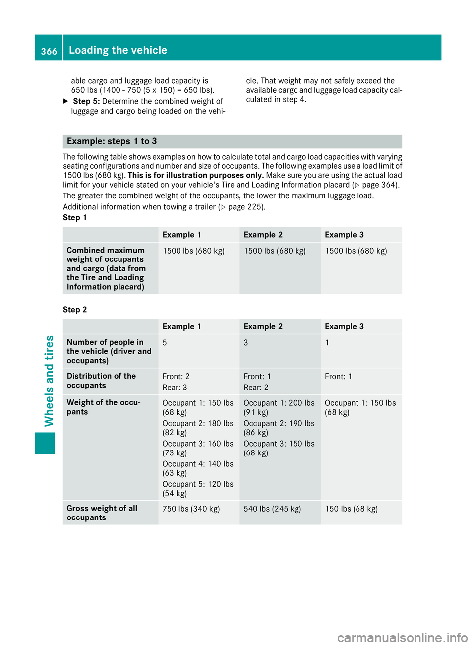
Example: steps 1 to 3
The following table shows examples on how to calculate total and cargo load capacities with varying
seating configurations and number and size of occupants. The following examples use a load limit of
1500 lbs (680 kg).
This is for illustration purposes only. Make sure you are using the actual load
limit for your vehicle stated on your vehicle's Tire and Loading Information placard (
Ypage 364).
The greater the combined weight of the occupants, the lower the maximum luggage load.
Additional information when towing a trailer (
Ypage 225).
Step 1
Example 1Example 2Example 3
Combined maximum
weight of occupants
and cargo (data from
the Tire and Loading
Information placard)1500 lbs (680 kg)1500 lbs (680 kg)1500 lbs (680 kg)
Step 2
Example 1Example 2Example 3
Number of people in
the vehicle (driver and
occupants)531
Distribution of the
occupantsFront: 2
Rear: 3Front: 1
Rear: 2Front: 1
Weight of the occu-
pantsOccupant 1: 150 lbs
(68 kg)
Occupant 2: 180 lbs
(82 kg)
Occupant 3: 160 lbs
(73 kg)
Occupant 4: 140 lbs
(63 kg)
Occupant 5: 120 lbs
(54 kg)Occupant 1: 200 lbs
(91 kg)
Occupant 2: 190 lbs
(86 kg)
Occupant 3: 150 lbs
(68 kg)Occupant 1: 150 lbs
(68 kg)
Gross weight of all
occupants750 lbs (340 kg)540 lbs (245 kg)150 lbs (68 kg)
366Loading the vehicle
Wheels and tires
Page 376 of 398
Sidewall
The part of the tire between the tread and the
bead.
Weight of optional extras
The combined weight of those optional extras
that weigh more than the replaced standard
parts and more than 2.3 kg (5 lbs). These
optional extras, such as high-performance
brakes, level control, a roof rack or a high-per-
formance battery, are not included in the curb
weight and the weight of the accessories.
TIN (Tire Identification Number)
This is a unique identifier which can be used by
a tire manufacturer to identify tires, for example
for a product recall, and thus identify the pur-
chasers. The TIN is made up of the manufactur-
er's identity code, tire size, tire type code and
the manufacturing date.
Load bearing index
The load bearing index (also load index) is a code
that contains the maximum load bearing capa-
city of a tire.
Traction
Traction is the result of friction between the tires
and the road surface.
TWR (Tongue Weight Rating)
The TWR specifies the maximum permissible
weight that the ball coupling of the trailer tow
hitch can support.
Treadwear indicators
Narrow bars (tread wear bars) that are distrib-
uted over the tire tread. If the tire tread is level
with the bars, the wear limit ofáin (1.6 mm)
has been reached.
Occupant distribution
The distribution of occupants in a vehicle at their
designated seating positions.
Total load limit
Nominal load and luggage load plus 68 kg
(150 lbs) multiplied by the number of seats in
the vehicle.
Changing a wheel
Flat tire
The "Breakdown assistance" section
(Ypage 339) contains information and notes on
how to deal with a flat tire. Information on driv-
ing with MOExtended tires in the event of a flat
tire can be found under "MOExtended tires (tires
with run-flat characteristics" (
Ypage 340).
Vehicles with an emergency spare wheel: in
the event of a flat tire, mount the emergency
spare wheel according to the description under "Mounting a wheel" (
Ypage 375).
Rotating the wheels
GWARNING
Interchanging the front and rear wheels may
severely impair the driving characteristics if
the wheels or tires have different dimensions. The wheel brakes or suspension components
may also be damaged. There is a risk of acci-
dent.
Rotate front and rear wheels only if the wheels and tires are of the same dimensions.
!On vehicles equipped with a tire pressure
monitor, electronic components are located
in the wheel.
Tire-mounting tools should not be used near
the valve. This could damage the electronic
components.
Only have tires changed at a qualified spe-
cialist workshop.
Always observe the instructions and safety
notes in the "Mounting a wheel" section
(
Ypage 375).
The wear patterns on the front and rear tires
differ, depending on the operating conditions.
Rotate the wheels before a clear wear pattern
has formed on the tires. Front tires typically
wear more on the shoulders and the rear tires in
the center.
On vehicles that have the same size front and
rear wheels, you can rotate the wheels accord-
ing to the intervals in the tire manufacturer's
warranty book in your vehicle documents. If no
warranty book is available, the tires should be
rotated every 3,000 to 6,000 miles (5,000 to
10,000 km). Depending on tire wear, this may
374Changing a wheel
Wheels and tires
Page 381 of 398
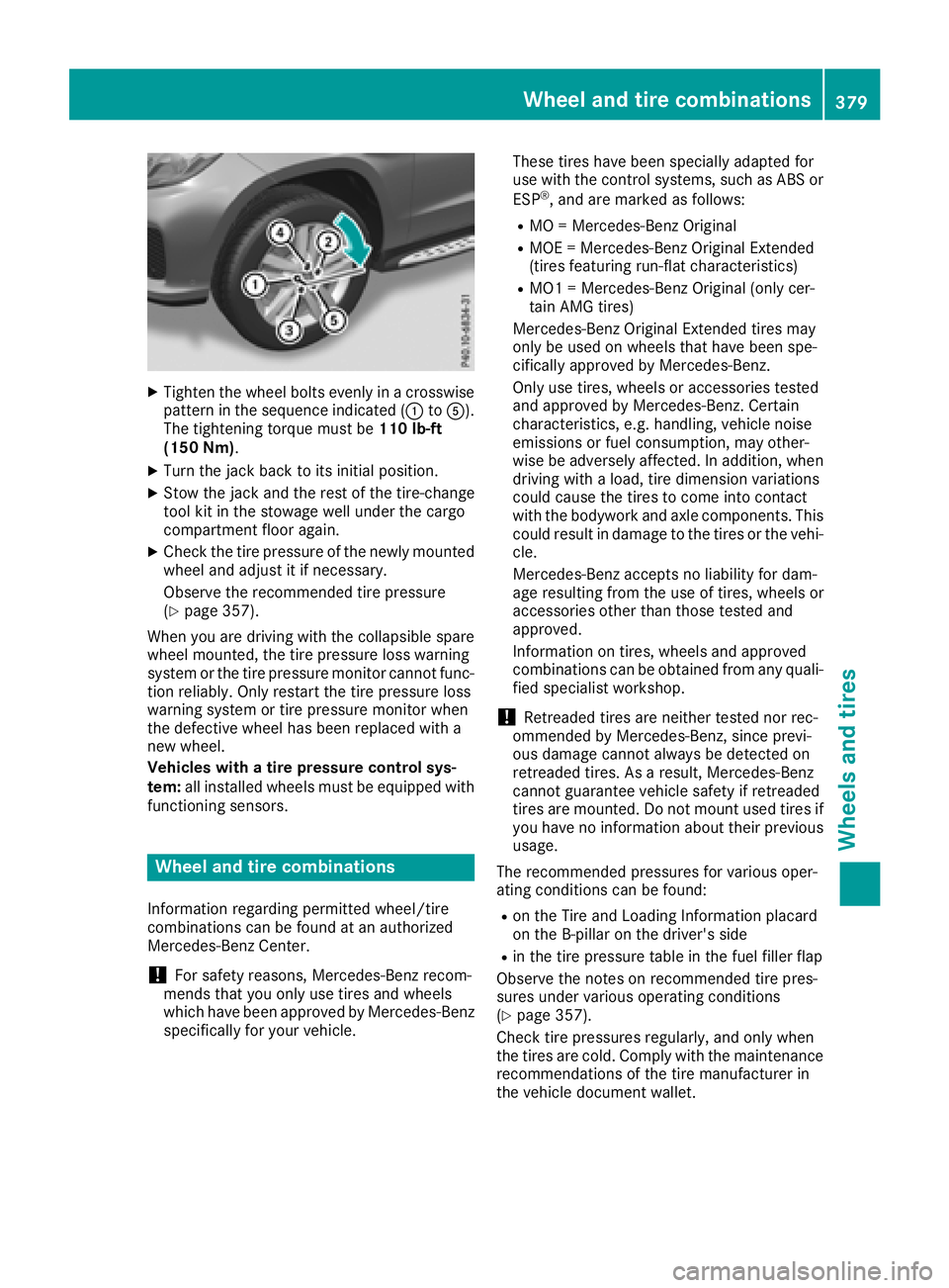
XTighten the wheel bolts evenly in a crosswisepattern in the sequence indicated (: toA).
The tightening torque must be 110 lb-ft
(150 Nm).
XTurn the jack back to its initial position.
XStow the jack and the rest of the tire-change
tool kit in the stowage well under the cargo
compartment floor again.
XCheck the tire pressure of the newly mounted
wheel and adjust it if necessary.
Observe the recommended tire pressure
(
Ypage 357).
When you are driving with the collapsible spare
wheel mounted, the tire pressure loss warning
system or the tire pressure monitor cannot func-
tion reliably. Only restart the tire pressure loss
warning system or tire pressure monitor when
the defective wheel has been replaced with a
new wheel.
Vehicles with a tire pressure control sys-
tem: all installed wheels must be equipped with
functioning sensors.
Wheel and tire combinations
Information regarding permitted wheel/tire
combinations can be found at an authorized
Mercedes-Benz Center.
!For safety reasons, Mercedes-Benz recom-
mends that you only use tires and wheels
which have been approved by Mercedes-Benz
specifically for your vehicle. These tires have been specially adapted for
use with the control systems, such as ABS or
ESP
®, and are marked as follows:
RMO = Mercedes-Benz Original
RMOE = Mercedes-Benz Original Extended
(tires featuring run-flat characteristics)
RMO1 = Mercedes-Benz Original (only cer-
tain AMG tires)
Mercedes-Benz Original Extended tires may
only be used on wheels that have been spe-
cifically approved by Mercedes-Benz.
Only use tires, wheels or accessories tested
and approved by Mercedes-Benz. Certain
characteristics, e.g. handling, vehicle noise
emissions or fuel consumption, may other-
wise be adversely affected. In addition, when
driving with a load, tire dimension variations
could cause the tires to come into contact
with the bodywork and axle components. This
could result in damage to the tires or the vehi- cle.
Mercedes-Benz accepts no liability for dam-
age resulting from the use of tires, wheels or
accessories other than those tested and
approved.
Information on tires, wheels and approved
combinations can be obtained from any quali-
fied specialist workshop.
!Retreaded tires are neither tested nor rec-
ommended by Mercedes-Benz, since previ-
ous damage cannot always be detected on
retreaded tires. As a result, Mercedes-Benz
cannot guarantee vehicle safety if retreaded
tires are mounted. Do not mount used tires if
you have no information about their previous
usage.
The recommended pressures for various oper-
ating conditions can be found:
Ron the Tire and Loading Information placard
on the B-pillar on the driver's side
Rin the tire pressure table in the fuel filler flap
Observe the notes on recommended tire pres-
sures under various operating conditions
(
Ypage 357).
Check tire pressures regularly, and only when
the tires are cold. Comply with the maintenance
recommendations of the tire manufacturer in
the vehicle document wallet.
Wheel and tire combinations379
Wheels and tires
Z
Page 383 of 398
Removing/stowing the emergency
spare wheel
Vehicles with a "Minispare" emergency
spare wheel under the cargo compart-
ment floor
Always observe the instructions and safety
notes in the "Mounting a wheel" section
(
Ypage 375).
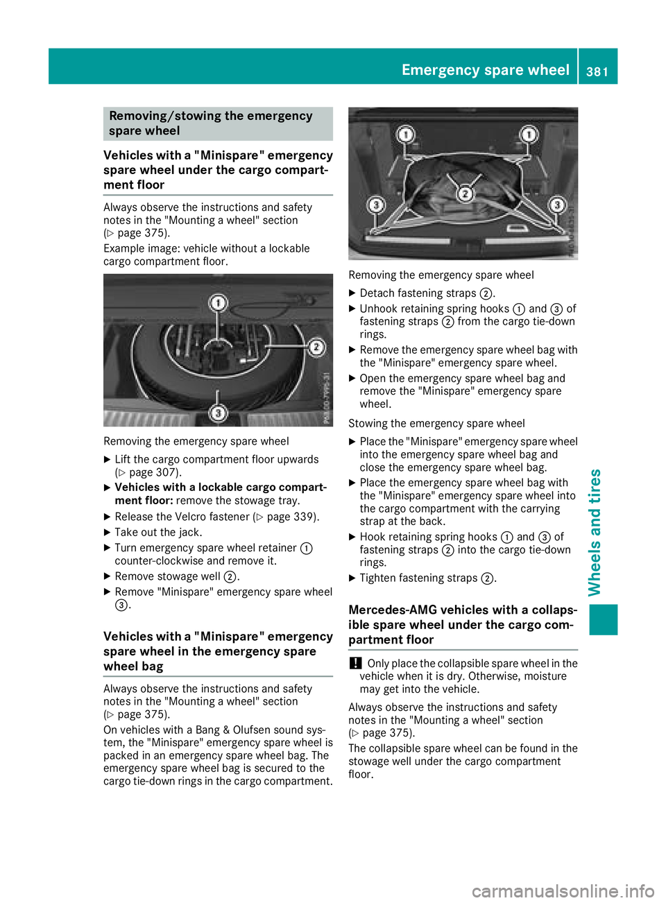
Example image: vehicle without a lockable
cargo compartment floor.
Removing the emergency spare wheel
XLift the cargo compartment floor upwards
(Ypage 307).
XVehicles with a lockable cargo compart-
ment floor: remove the stowage tray.
XRelease the Velcro fastener (Ypage 339).
XTake out the jack.
XTurn emergency spare wheel retainer :
counter-clockwise and remove it.
XRemove stowage well ;.
XRemove "Minispare" emergency spare wheel
=.
Vehicles with a "Minispare" emergency
spare wheel in the emergency spare
wheel bag
Always observe the instructions and safety
notes in the "Mounting a wheel" section
(
Ypage 375).
On vehicles with a Bang & Olufsen sound sys-
tem, the "Minispare" emergency spare wheel is
packed in an emergency spare wheel bag. The
emergency spare wheel bag is secured to the
cargo tie-down rings in the cargo compartment.
Removing the emergency spare wheel
XDetach fastening straps ;.
XUnhook retaining spring hooks :and =of
fastening straps ;from the cargo tie-down
rings.
XRemove the emergency spare wheel bag with
the "Minispare" emergency spare wheel.
XOpen the emergency spare wheel bag and
remove the "Minispare" emergency spare
wheel.
Stowing the emergency spare wheel
XPlace the "Minispare" emergency spare wheel
into the emergency spare wheel bag and
close the emergency spare wheel bag.
XPlace the emergency spare wheel bag with
the "Minispare" emergency spare wheel into
the cargo compartment with the carrying
strap at the back.
XHook retaining spring hooks :and =of
fastening straps ;into the cargo tie-down
rings.
XTighten fastening straps ;.
Mercedes-AMG vehicles with a collaps-
ible spare wheel under the cargo com-
partment floor
!Only place the collapsible spare wheel in the
vehicle when it is dry. Otherwise, moisture
may get into the vehicle.
Always observe the instructions and safety
notes in the "Mounting a wheel" section
(
Ypage 375).
The collapsible spare wheel can be found in the
stowage well under the cargo compartment
floor.
Emergency spare wheel381
Wheels and tires
Z
Page 384 of 398
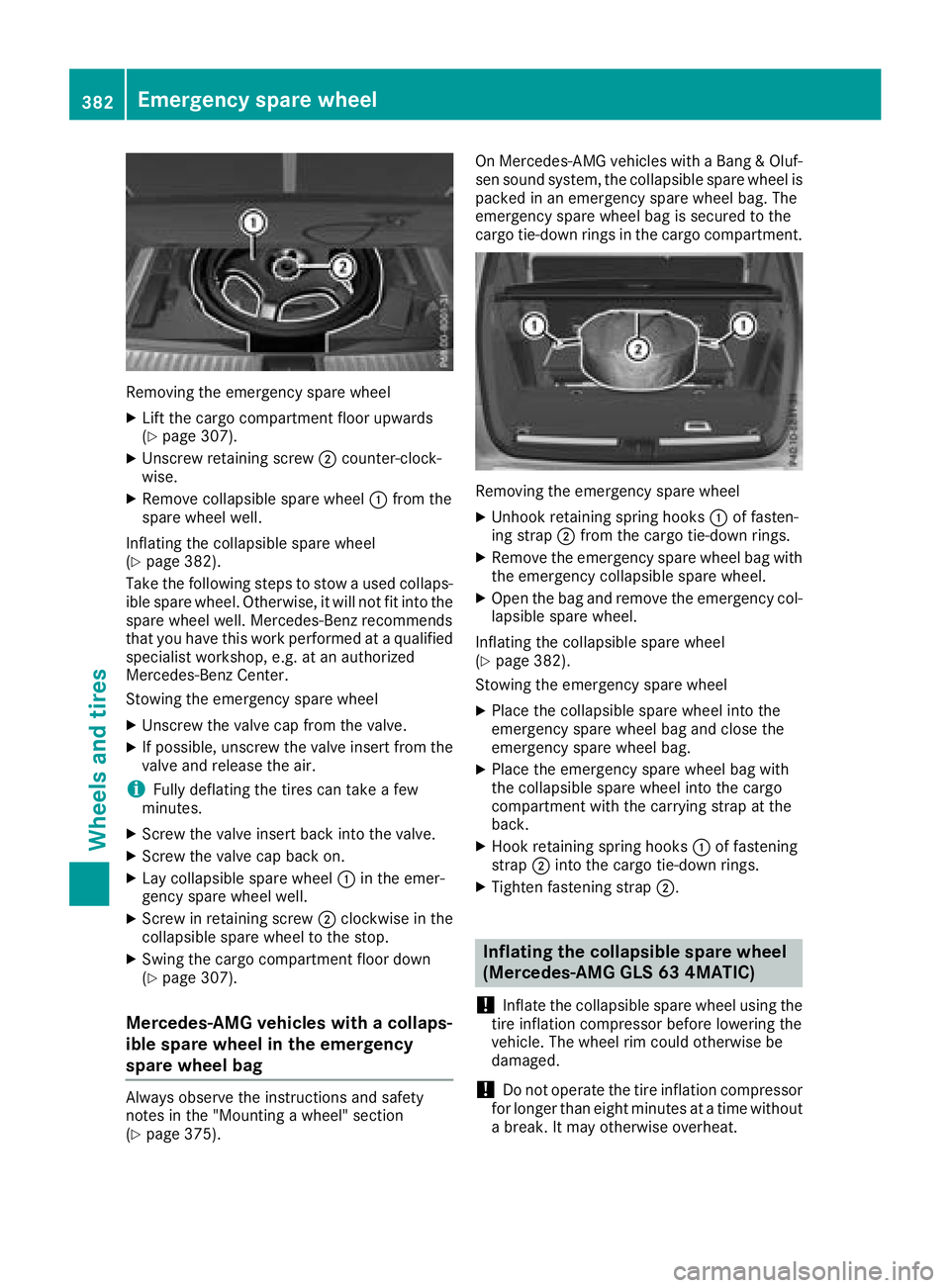
Removingth eemergenc yspar ewhee l
XLiftth ecargo compartmen tfloor upwards
(Ypage 307).
XUnscrew retaining screw ;counter-clock -
wise.
XRemove collapsible spar ewhee l: from th e
spar ewhee lwell.
Inflating th ecollapsible spar ewhee l
(
Ypage 382).
Tak eth efollowin gsteps to stow aused collaps -
ible spar ewheel. Otherwise, it will no tfit int oth e
spar ewhee lwell. Mercedes-Ben zrecommends
that you hav ethis wor kperformed at aqualified
specialist workshop, e.g. at an authorize d
Mercedes-Ben zCenter.
Stowin gth eemergenc yspar ewhee l
XUnscrew th evalv ecap from th evalve.
XIf possible, unscrew th evalv einsert from th e
valv eand release th eair.
iFull ydeflating th etires can tak e afew
minutes.
XScrew th evalv einsert bac kint oth evalve.
XScrew th evalv ecap bac kon .
XLay collapsible spar ewhee l: in th eemer-
gency spar ewhee lwell.
XScrew in retaining screw ;clockwise in th e
collapsible spar ewhee lto th estop.
XSwing th ecargo compartmen tfloor down
(Ypage 307).
Mercedes-AMG vehicles with a collaps-
ible spare wheel in the emergency
spare wheel bag
Always observ eth einstruction sand safet y
note sin th e"Mounting awheel" section
(
Ypage 375). On Mercedes-AM
Gvehicles wit h aBan g & Oluf -
sen soun dsystem, th ecollapsible spar ewhee lis
packe din an emergenc yspar ewhee lbag. The
emergenc yspar ewhee lbag is secured to th e
cargo tie-down rings in th ecargo compartment.
Removin gth eemergenc yspar ewhee l
XUnhoo kretaining spring hooks :of fasten-
ing strap ;from th ecargo tie-down rings.
XRemove th eemergenc yspar ewhee lbag wit h
th eemergenc ycollapsible spar ewheel.
XOpen th ebag and remove th eemergenc ycol-
lapsible spar ewheel.
Inflating th ecollapsible spar ewhee l
(
Ypage 382).
Stowin gth eemergenc yspar ewhee l
XPlaceth ecollapsible spar ewhee lint oth e
emergenc yspar ewhee lbag and close th e
emergenc yspar ewhee lbag.
XPlac eth eemergenc yspar ewhee lbag wit h
th ecollapsible spar ewhee lint oth ecargo
compartmen twit hth ecarryin gstrap at th e
back.
XHook retaining spring hooks :of fastenin g
strap ;intoth ecargo tie-down rings.
XTighte nfastenin gstrap ;.
Inflating the collapsible spare wheel
(Mercedes-AMG GLS 63 4MATIC)
!
Inflat eth ecollapsible spar ewhee lusin gth e
tire inflation compressor before lowering th e
vehicle. The whee lrim could otherwise be
damaged.
!Do no toperate th etire inflation compressor
for longer than eigh tminute sat atime without
a break. It may otherwise overheat.
382Emergency spare wheel
Wheels and tires
Page 385 of 398
The tire inflation compressor can be operated
again once it has cooled down.
Comply with the manufacturer's safety instruc-
tions on the tire inflation compressor label and
on the tire sealant bottle.
XMount the collapsible spare wheel as descri-
bed (Ypage 375).
The collapsible spare wheel must be mounted before it is inflated.
XRemove the tire inflation compressor from
the stowage space under the cargo compart-
ment floor (
Ypage 339).
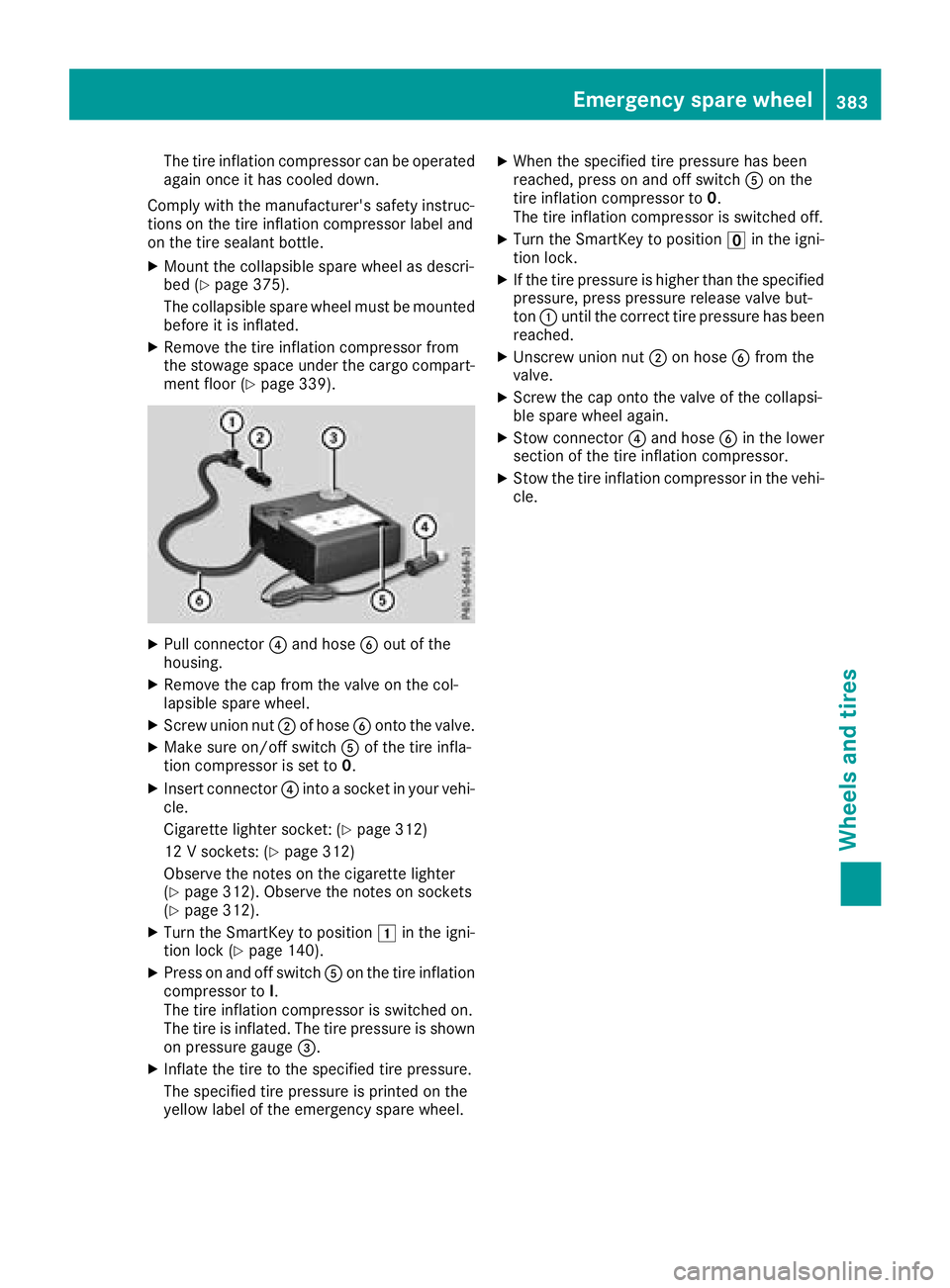
XPull connector ?and hose Bout of the
housing.
XRemove the cap from the valve on the col-
lapsible spare wheel.
XScrew union nut ;of hose Bonto the valve.
XMake sure on/off switch Aof the tire infla-
tion compressor is set to 0.
XInsert connector?into a socket in your vehi-
cle.
Cigarette lighter socket: (
Ypage 312)
12 V sockets: (
Ypage 312)
Observe the notes on the cigarette lighter
(
Ypage 312). Observe the notes on sockets
(Ypage 312).
XTurn the SmartKey to position 1in the igni-
tion lock (Ypage 140).
XPress on and off switch Aon the tire inflation
compressor to I.
The tire inflation compressor is switched on.
The tire is inflated. The tire pressure is shown
on pressure gauge =.
XInflate the tire to the specified tire pressure.
The specified tire pressure is printed on the
yellow label of the emergency spare wheel.
XWhen the specified tire pressure has been
reached, press on and off switch Aon the
tire inflation compressor to 0.
The tire inflation compressor is switched off.
XTurn the SmartKey to position uin the igni-
tion lock.
XIf the tire pressure is higher than the specified
pressure, press pressure release valve but-
ton :until the correct tire pressure has been
reached.
XUnscrew union nut ;on hose Bfrom the
valve.
XScrew the cap onto the valve of the collapsi-
ble spare wheel again.
XStow connector ?and hose Bin the lower
section of the tire inflation compressor.
XStow the tire inflation compressor in the vehi-
cle.
Emergency spare wheel383
Wheels and tires
Z
Page 397 of 398
Accelerate carefully and make sure that the
wheels do not spin when driving on steep ter-
rain.
iIf the load on the front axle is reduced when
pulling away on a steep uphill slope, the front
wheels have a tendency to spin. 4ETS recog-
nizes this and brakes the wheels accordingly.
The rear wheel torque is increased, making it
easier to drive off.
For further information about the maximum gra-
dient climbing ability, see (
Ypage 173).
Trailer tow hitch
Mounting dimensions
!
If you have a trailer tow hitch retrofitted,
changes to the cooling system and drive train
may be necessary, depending on the vehicle
type.
If you have a trailer tow hitch retrofitted,
observe the anchorage points on the chassis
frame.
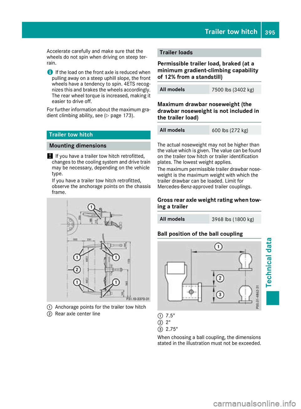
:Anchorage points for the trailer tow hitch
;Rear axle center line
Trailer loads
Permissible trailer load, braked (at a
minimum gradient-climbing capability
of 12% from a standstill)
All models7500 lbs (3402 kg)
Maximum drawbar noseweight (the
drawbar noseweight is not included in
the trailer load)
All models600 lbs (272 kg)
The actual noseweight may not be higher than
the value which is given. The value can be found
on the trailer tow hitch or trailer identification
plates. The lowest weight applies.
The maximum permissible trailer drawbar nose-
weight is the maximum weight with which the
trailer drawbar can be loaded. Limit for
Mercedes-Benz-approved trailer couplings.
Gross rear axle weight rating when tow-
ing a trailer
All models3968 lbs (1800 kg)
Ball position of the ball coupling
:7.5"
;2"
=2.75"
When choosing a ball coupling, the dimensions
stated in the illustration must not be exceeded.
Trailer tow hitch395
Technical data
Z