2018 MERCEDES-BENZ E-CLASS COUPE radio
[x] Cancel search: radioPage 5 of 593

Symbols
........................................................ 5At
agl ance .................................................... 6
Cockpit ........................................................... 6
Wa rning and indicator lamps .......................... 8
Overhead control panel ................................ 12
Door control panel and seat adjustment ....... 14
Emergencies and breakdowns ...................... 16Digital Owner's Manual
.............................18
Calling up the Digital Owner's Manual ..........18 Genera
l notes............................................. 19
Pr otection of the environment ......................19
Ta ke -ba ckof end-of-life vehicles ...................19
Mercedes-Benz Genuine Parts ......................20
Owner's Manual ............................................ 21
Operating saf ety .......................................... .21
Declaration of Conformity ............................ 23
Diagno stics connection ................................ 24
Qualified specialist workshop ....................... 25
Ve hicle registration ....................................... 25
Cor rect use of theve hicle ............................25 Information on
the REA CHregulation ........... 26
Implied warranty .......................................... .26
QR code forre scue card ...............................26
Data storage .................................................26
Copyright ...................................................... 29 Occupant saf
ety......................................... 30
Re stra int sy stem ...........................................30
Seat belts ..................................................... 32
Airbags ......................................................... 38
PRE-SAFE ®
sy stem ....................................... 45
Safely transporting children in theve hi‐
cle ................................................................46
No tes on pets in theve hicle .........................70 Opening and closing
.................................. 71
Ke y ................................................................ 71
Doo rs............................................................ 75
Boot .............................................................. 80
Ro ller sunblinds ............................................ 85
Side windo ws............................................... 86
Sliding sunroof ............................................. 90
Anti-theft pr otection .....................................95 Seats and
stowing ..................................... 98
No tes on the cor rect driver's seat posi‐
tion ............................................................... 98
Seats ............................................................ 99
St eering wheel ............................................ 109
Easy entry and exitfeature .......................... 111
Operating the memory function .................. 11 2
St ow age areas ............................................ .113
Cup holders ................................................ 121
Ashtr ayand cigar ette lighter ...................... .123
Soc kets ....................................................... 124
Wi reless charging of the mobile phone
and connection with theex terior aerial .......1 24
Fitting and removing thefloor mats ............ 12 6 Light and sight
......................................... 12 8
Exterior lighting .......................................... 12 8
Interior lighting ........................................... 13 5
Wi ndsc reen wipers and windscreen
wa sher sy stem ............................................ 13 6
Mir rors ........................................................ 14 0
Operating the sun visors ............................. 14 3
Area pe rmeable toradio wav es on the
windscreen ................................................ .143 2
Contents
Page 26 of 593

Ve
hicles with a 48 V on-board electrical sy stem
conta in high voltage components. These compo‐
nents are mar ked with a high voltage label: All
workon high voltage components must be
car ried out at a qualified specialist workshop. Declaration of Conformity
Electromagnetic compatibility
The electromagnetic compatibility of
theve hicle
components has been checked and certified
according tothe cur rently valid version of Regu‐
lation UN R10. Wire
lessvehicle comp onents The
following information applies toall compo‐
nents of theve hicle and the information sy stems
and communication devices integrated into the
ve hicle which recei veand/or transmit radio
wav es:
The components of this vehicle that recei ve
and/or transmit radio wav es are compliant with
th e basic requ irements and all other releva nt
conditions of Directi ve2014 /53/EU. You can
obtain fur ther information from a Mercedes-Benz
Service Centre. Jack
Copy and translation of
the original declaration
of confo rmity:
Original CE declaration of conformity
Bosal Hun gary KFT hereby decla resth at
Jack: Daimler jack products
with
serial no.: A 205 580 00 00
A
21 2 580 00 18
A 21 2 580 04 18
A 231 580 00 18 complies wi
th thefo llowing directives:
EU2006/42/EC
The following standard has been obse rved dur‐
ing de velopmen t:EN ISO 12100
This publication pr ovides authorisation to
inspect (equipment), prepare tech nical docu‐
mentation and pr ovide authentication.
The jack may not be used before all the de tails
ha ve been defined and con firm ed, as described
in the Owner's Manual forth e jac k.Ifth is is not
th e case, the jack may not be used.
[Signature] [Signature]
[Name of signatory]
R&D Manager BHUK [Name of signatory]
Project Engineer General no
tes23
Page 77 of 593

Mercedes-Benz
recommends that you ha vethe
battery replaced at a qualified specialist work‐
shop. #
Remo vethe emer gency key ( → page 73). #
Press release button 2down fully and slide
co ver1 inthe direction of the ar row. #
Fold out co ver1 inthe direction of the
ar row and remo ve. #
Remo vebattery compartment 3and take
out the dischar ged batter y. #
Insert the new battery into battery compart‐
ment 3. Obser vethe positive pole marking
in the battery compartment and on the bat‐
te ry when doing this. #
Push in battery compartment 3. #
Re-attach co ver1 and push it until it
engages. Problems with
thekey Problem
Possible causes/consequences and M
MSolutions
Yo u can no lon ger lock or unlock the
ve hicle. Po
ssible causes:
R The key bat tery iswe ak or dischar ged.
R There is inter fere nce from a po werful radio signal source.
R The key is faulty. 74
Opening and closing
Page 81 of 593

#
Tounlo cktheve hicle: touch the inner sur‐
fa ce of the door handle. #
Tolock theve hicle: touch sensor sur face
1 or2. #
Convenience closing: touch recessed sen‐
sor su rface 2until the closing procedure is
comple te. %
Further information on con venience closing
(→ page 88).
If yo u open the boot lid from outside it is auto‐
matically unloc ked. Problems with KEYLESS-GO
Problem
Possible causes/consequences and M
MSolutions
Yo u can no lon ger lock or unlock the
ve hicle using KEYLESS-GO. Po
ssible causes:
R The key functions ha vebeen deactivated (→ page72).
R The key bat tery iswe ak or dischar ged.
R There is inter fere nce from a po werful radio signal source.
R The key is faulty. #
Activate theke y functions (→ page72). #
Check the battery using the battery check lamp and replace if necessary (→ page73). #
Use the emer gency keyto unlo ckor lock theve hicle (→ page73). #
Have theve hicle and keych ecked at a qualified specialist workshop. 78
Opening and closing
Page 146 of 593

Operating
the sun visors
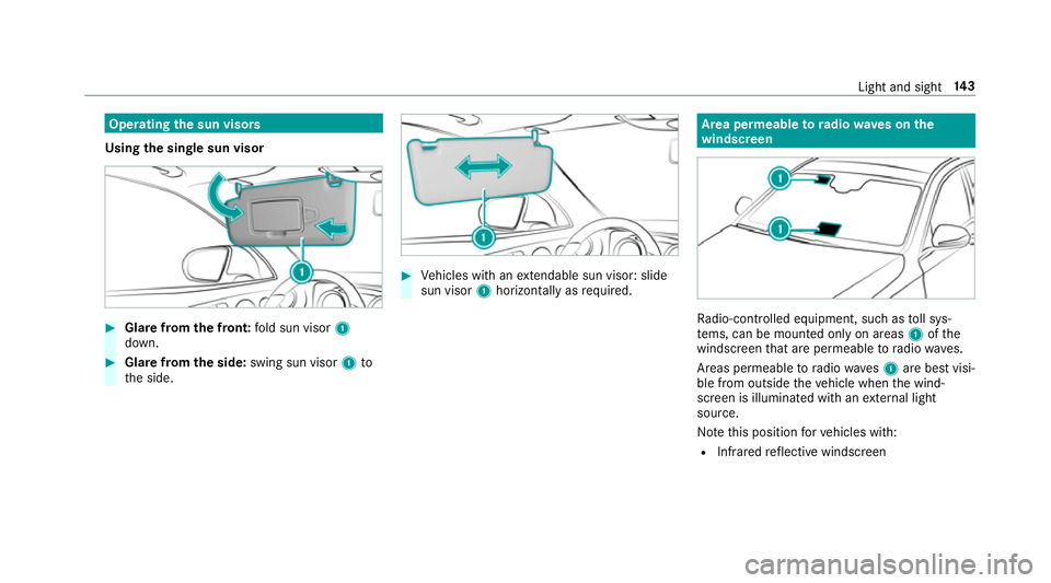
Using the single sun visor #
Glarefrom the front: fold sun visor 1
down. #
Glare from the side: swing sun visor 1to
th e side. #
Vehicles with an extendable sun visor: slide
sun visor 1horizontal lyas requ ired. Area permeable
to radiowav es on the
windscreen Ra
dio-contro lled equipment, such as toll sys‐
te ms, can be mounted only on areas 1ofthe
windscreen that are permeable toradio wav es.
Areas permeable toradio wav es1 are best visi‐
ble from outside theve hicle when the wind‐
screen is illuminated with an extern al light
source.
No tethis position forve hicles with:
R Infra redre flective windscreen Light and sight
14 3
Page 188 of 593

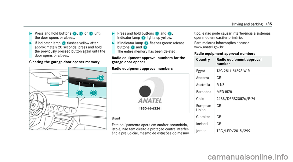
#
Press and hold buttons 1,2or3 until
th e door opens or closes. #
If indicator lamp 4flashes yellow af ter
appr oximately 20 seconds: press and hold
th e pr eviously pressed button again until the
door opens or closes.
Clearing thega rage door opener memo ry #
Press and hold buttons 1and 3.
Indicator lamp 4lights up yello w. #
If indicator lamp 4flashes green: release
buttons 1and 3.
The entire memo ryhas been dele ted.
Ra dio equipment appr oval numbers for the
ga rage door opener
Ra dio equipment appr oval numbers Brazil
Es te equipamento opera em caráter secundário,
is to é, não tem direito à pr oteção contra inter fer‐
ência prejudicial, mesmo de es tações do mesmo tipo, e não pode causar inter
ferê ncia a si stemas
operando em caráter primário.
Pa ra maio res informações acessar
www.anatel.go v.br
Ra dio equipment appr oval numbers Countr
yRadio equipment appr oval
number
Egyp tT AC.25 111 51293.WIR
Andor ra CE
Au stra lia R-NZ
Barbados MED1 578
Chile 2488/DFRS205 76/F-74
European
Union CE
Gibral tarCE
Iceland CE
Jordan TRC/LPD/20 15/299 Driving and pa
rking 18 5
Page 189 of 593

Count
ryRadio equipment appr oval
number
Canada IC: 4112 A-MUAHL5
Ku wa it CE
Liechten‐
st ein CE
Mexico RCPGEMU15-0448
Monaco CE
New Zea‐
land R-
NZ
Nor wayCE
Ru ssian
Fe dera‐
tion Not
requ ired
Saudi Ara‐
bia TA
10525
Switzer‐
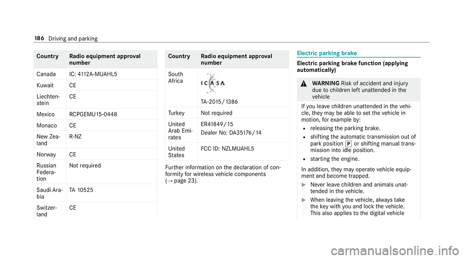
land CE Countr
yRadio equipment appr oval
number
South
Africa TA
-20 15/1386
Tu rkey Notrequ ired
Uni ted
Arab Emi‐
ra tes ER4
1849/15
Dealer No: DA35176/14
United
St ates FCC ID: NZLM
UAHL5 Fu
rther information on the declaration of con‐
fo rm ity for wireless vehicle components
(→ page 23). Electric parking brake
Electric parking brake function (applying
automatically) &
WARNING Risk of accident and inju ry
due tochildren left unat tended in the
ve hicle
If yo u lea vechildren unat tended in theve hi‐
cle, they may be able toset theve hicle in
motion, forex ample by:
R releasing the parking brake.
R shifting the automatic transmission out of
park position jor shifting manual trans‐
mission into idle position.
R starting the engine.
In addition, they may operate vehicle equip‐
ment and become trapped. #
Never lea vechildren and animals unat‐
te nded in theve hicle. #
When leaving theve hicle, alw aysta ke
th eke y with you and lock theve hicle.
This also applies tothe digital vehicle 18 6
Driving and pa rking
Page 265 of 593

~
Rejects/ends a call
5 ò Calls up the home screen
6 Touch Control multimedia sy stem
7 % Back button (press and hold) Operating
the on-boa rdcompu ter &
WARNING Risk of di stra ction from infor‐
mation sy stems and communications
equipment
If yo u operate information and communica‐
tion equipment integ rated in theve hicle
when driving, you will be distracted from the
traf fic situation. This could also cause youto
lose control of theve hicle. #
Only operate this equipment when the
traf fic situation permits. #
Ifyo u cannot be sure of this, stop the
ve hicle whilst paying attention toroad
and traf fic conditions and ope rate the
equipment with theve hicle stationar y. Obser
vethe legal requ irements forth e count ry
in which you are cur rently driving when you
operate the on-board computer.
% The on-board computer displa ysappear on
th e multifunction display (→ page 264). The on-board computer can be operated using
th e left-hand Touch Control 2and the left-hand
back/home button 1. When
the on-board computer is being operated,
dif fere nt acoustic signals sound as operating
fe edbac k,e.g. when the end of a list is reached
or when you are sc rolling thro ugh a list.
The following menus are available:
R Service
R Assistance
R Trip
R Navigation
R Radio
R Media
R Telephone
R HUD
R Vehicles with an instrument display in
th e widescreen cockpit: Design
The menus can be called up from the menu bar
on the multifunction displa y. #
Tocall up the menu bar: pressthe back
button on the left 1until the menu bar is
displa yed. 262
Instrument Display and on-board computer