2018 MERCEDES-BENZ AMG GT ROADSTER engine
[x] Cancel search: enginePage 279 of 409
All
vehicles
* NO
TEDama gecaused bynumerous or
ex tended attem ptsto start the engine Nume
rous or extended attem ptsto start the
engine may damage the catalytic con verter
due tonon-combu sted fuel. #
Avoid numerous and extended attem pts
to start the engine. Obser
vethefo llowing points during starting
assis tance and when charging the battery:
R Only use undamaged jump lead/charging
cables with a suf ficient cross-section and
insula tedte rm inal clamps.
R Non- insulated parts of thete rm inal clamps
must not come into con tact wi thother me tal
parts while the jump lead/charging cable is
connected tothe battery/jump-s tart connec‐
tion point.
R The jump lead/charging cable must not
come into contact wi thany parts which may
mo vewhen the engine is running. R
Alw ays make sure that nei ther you nor the
battery is elect rostatically charge d.
R Keep away from fire and naked flames.
R Do not lean overth e batter y.
Obser vethe additional following points when
ch arging the battery:
R Only use battery charge rs tested and
appr oved for Mercedes-Benz.
R Read the battery charge r's operating instruc‐
tions before charging the batter y.
Obser vethe additional following points during
st arting assis tance:
R Starting assis tance may only be pr ovided
using batteries with a nominal voltage of
12 V.
R The vehicles must not touch.
R Petrol engine: only acceptstarting assis‐
ta nce if the engine and exhaust sy stem are
cold. St
arting assi stance and charging the12 V
battery Re
quirements:
R The vehicle is secured with the electric park‐
ing brake.
R Vehicles with automatic transmission: the
transmission is in position j.
R The ignition and all electrical consumers are
switched off.
R The bonnet is open. 276
Breakdown assis tance
Page 280 of 409
#
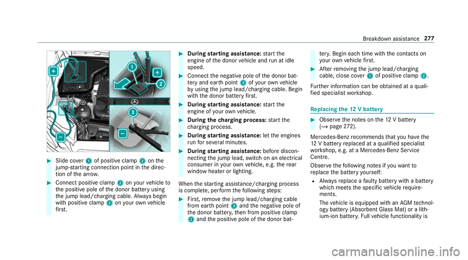
Slide co ver1 of positive clamp 2onthe
jump-s tarting connection point in the direc‐
tion of the ar row. #
Connect positive clamp 2onyour vehicle to
th e positive pole of the donor battery using
th e jump lead/charging cable. Alw ays begin
with positive clamp 2onyour ow nve hicle
fi rs t. #
During starting assi stance: start the
engine of the donor vehicle and run at idle
speed. #
Connect the negative pole of the donor bat‐
te ry and ear thpoint 3ofyour ow nve hicle
by using the jump lead/charging cable. Begin
with the donor battery firs t. #
During starting assi stance: start the
engine of your ow nve hicle. #
During thech arging process: start the
ch arging process. #
During starting assi stance: letthe engines
ru nfo r se veral minutes. #
During starting assi stance: before discon‐
necting the jump lead, switch on an electrical
consumer in your ow nve hicle, e.g. there ar
wind owheater or lighting.
When thest arting assis tance/charging process
is compl ete, per form thefo llowing steps: #
First,re mo vethe jump lead/charging cable
from ear thpoint 3and the negative pole of
th e donor batter y,then from positive clamp
2 and the positive pole of the donor bat‐ te
ry. Begin ea chtime wi th the conta cts on
yo ur ow nve hicle firs t. #
Afterre moving the jump lead/charging
cable, close co ver1 of positive clamp 2.
Fu rther information can be obtained at a quali‐
fi ed specialist workshop. Re
placing the 12V battery #
Obser vethe no tes on the12 V battery
(/ page 272).
Mercedes-Benz recommends that you ha vethe
12 V battery replaced at a qualified specialist
wo rkshop, e.g. at a Mercedes-Benz Service
Centre.
Obser vethefo llowing no tes if youwa ntto
re place the battery yourself:
R Alw aysre place a faulty bat tery with a battery
which meets the specific vehicle require‐
ments.
The vehicle is equipped with an AGMtech nol‐
ogy battery (Absorbent Glass Mat) or a li th‐
ium-ion batter y.Fu llve hicle functionality is Breakdown assis
tance 277
Page 282 of 409
To
wing theve hicle with bo thaxles on the
gr ound #
Obser vethe no tes on the permitted towing
me thods (/ page278). #
Make sure that the battery is connected and
ch arge d.
Obser vethefo llowing points when the battery is
dischar ged:
R the engine cann otbe star ted
R the electric parking brake cann otbe released
or applied
R vehicles with automatic transmission: the
automatic transmission cannot be shif tedto
position iorj.
% Vehicles with automatic transmission: if
th e automatic transmission cann otbe shif‐
te dto position i, orthe multifunction dis‐
play in the instrument clus ter does not show
anything, ha vetheve hicle transpor tedaw ay
( / page 280). A towing vehicle with lifting
equipment is requiredforve hicle transpor ta‐
tion. *
NO
TEDama gedue to to wing away at
exc essively high speeds or over long dis‐
ta nces The driv
etra in could be damaged when tow‐
ing at excessively high speeds or over long
dis tances. #
Atowing speed of 50 km/h must not
be exc eeded. #
Atowing dis tance of 50 km mu stnot be
exc eeded. &
WARNING Risk of accident when towing
a ve hicle which is too heavy
If th eve hicle being tow- star ted or towed
aw ay is heavier than the permissible gross
mass, thefo llowing situations can occur:
R theto wing eye may become de tach ed.
R the car/t railer combination may swer ve
or eve nove rturn. #
If ano ther vehicle is tow- star ted or
to we daw ay, its weight must not exceed th
e permissible gross mass of your own
ve hicle. If a
vehicle must be tow star ted or towe daw ay,
its permissible gross mass must not exceed the
permissible gross mass of theto wing vehicle. #
Information on the permissible gross mass of
th eve hicle can be found on theve hicle iden‐
tification plate (/ page 306). #
Vehicles with automatic transmission: do
not open the driver's door or front passenger
door, otherwise the automatic transmission
automatically shifts toposition j. #
Fittheto wing eye (/ page 282). #
Fasten theto w bar.
* NO
TEDama gedue toincor rect connec‐
tion #
Only connect theto w rope or tow bar to
th eto wing eyes. #
Deactivate the automatic locking mechanism
(/ page 63). Breakdown assis
tance 279
Page 285 of 409
Installing
theto wing eye #
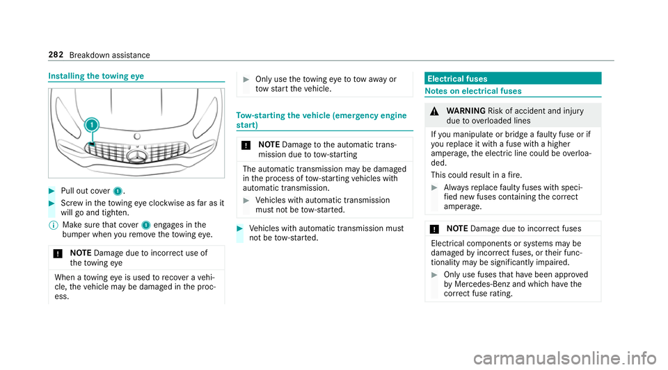
Pull out co ver1. #
Screw intheto wing eyeclockwise as far as it
will go and tighten.
% Make sure that co ver1 engages in the
bumper when youre mo vetheto wing eye.
* NO
TEDama gedue toincor rect use of
th eto wing eye When a
towing eye is used toreco ver a vehi‐
cle, theve hicle may be damaged in the proc‐
ess. #
Only use theto wing eyeto to waw ay or
to w start theve hicle. To
w- starting theve hicle (eme rgency engine
st art) *
NO
TEDama getothe automatic trans‐
mission due to tow-starting The automatic transmission may be damaged
in the process of tow- starting vehicles with
automatic transmission. #
Vehicles with automatic transmission
must not be tow- star ted. #
Vehicles with automatic transmission must
not be tow- star ted. Electrical fuses
Note
s on electrical fuses &
WARNING Risk of accident and inju ry
due to ov erloaded lines
If yo u manipulate or bridge a faulty fuse or if
yo ure place it with a fuse with a higher
amperage, the electric line could be overloa‐
ded.
This could result in a fire. #
Alw aysre place faulty fuses with speci‐
fi ed new fuses conta iningthe cor rect
amperage. *
NO
TEDama gedue toincor rect fuses Electrical components or sy
stems may be
damaged byincor rect fuses, or their func‐
tionality may be significant lyimpaired. #
Only use fuses that ha vebeen appr oved
by Mercedes-Benz and which ha vethe
cor rect fuse rating. 282
Breakdown assi stance
Page 301 of 409
R
The vehicle is not on a slope.
R The vehicle is on solid, non-slippery and le vel
ground. #
Apply the electric parking brake manually. #
Movethe front wheels tothest ra ight-ahead
position. #
Shift the transmission toposition j. #
Switch off the engine. #
Make sure that the engine cann otbe star ted. #
Place choc ks orother suitable items under
th e front and rear of the wheel that is diago‐
nally opposite the wheel you wish tochange. #
Remo vethe hub caps if necessary . #
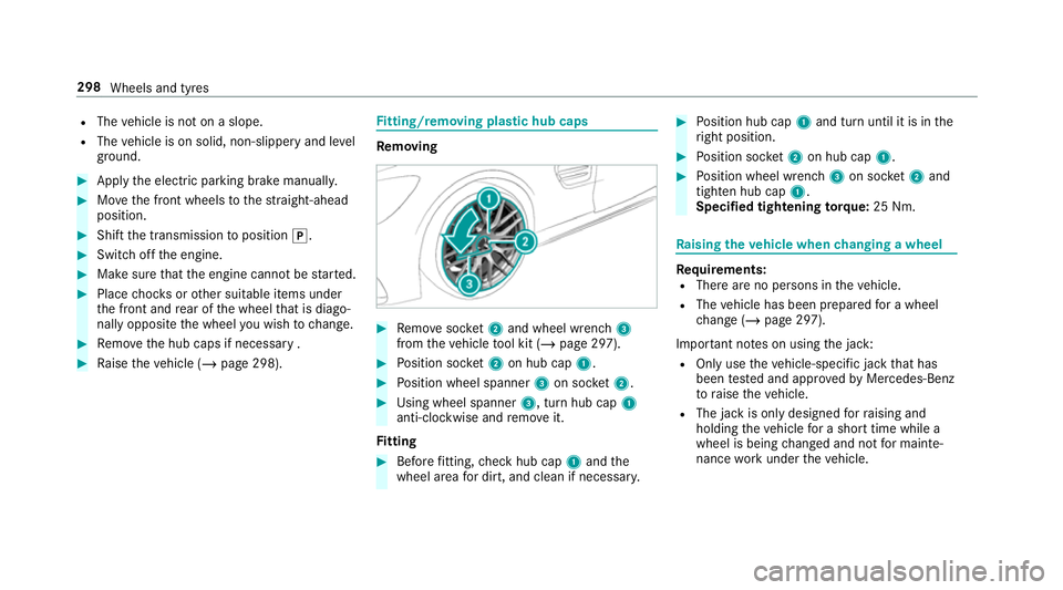
Raise theve hicle (/ page 298). Fi
tting/ removing pla stic hub caps Re
moving #
Remo vesoc ket2 and wheel wrench 3
from theve hicle tool kit (/ page 297). #
Position soc ket2 on hub cap 1. #
Position wheel spanner 3on soc ket2. #
Using wheel spanner 3, turn hub cap1
anti-clo ckwise and remo veit.
Fi tting #
Before fitting, check hub cap 1and the
wheel area for dirt, and clean if necessar y. #
Position hub cap 1and turn until it is in the
ri ght position. #
Position soc ket2 on hub cap 1. #
Position wheel wrench 3on soc ket2 and
tighten hub cap 1.
Speci fied tigh tening torq ue: 25 Nm. Ra
ising theve hicle when changing a wheel Re
quirements:
R There are no persons in theve hicle.
R The vehicle has been prepared for a wheel
ch ange (/ page 297).
Important no tes on using the jack:
R Only use theve hicle-specific jack that has
been tested and appr oved byMercedes-Benz
to raise theve hicle.
R The jack is only designed forra ising and
holding theve hicle for a short time while a
wheel is being changed and not for mainte‐
nance workunder theve hicle. 298
Wheels and tyres
Page 302 of 409
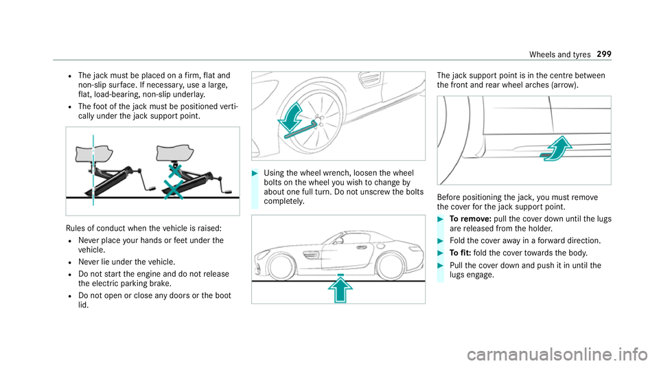
R
The jack must be placed on a firm ,fl at and
non-slip sur face. If necessar y,use a lar ge,
fl at, load-bearing, non-slip unde rlay.
R The foot ofthe jack must be positioned verti‐
cally under the jack support point. Ru
les of conduct when theve hicle is raised:
R Never place your hands or feet under the
ve hicle.
R Never lie under theve hicle.
R Do not start the engine and do not release
th e electric parking brake.
R Do not open or close any doors or the boot
lid. #
Using the wheel wrench, loosen the wheel
bolts on the wheel you wish tochange by
about one full turn. Do not unscr ewthe bolts
comple tely. The jack support point is in
the cent rebetween
th e front and rear wheel ar ches (ar row). Before positioning
the jac k,you must remo ve
th e co verfo rth e jack support point. #
Toremo ve:pull the co ver down until the lugs
are released from the holder. #
Foldthe co veraw ay in a forw ard direction. #
Tofit: fold the co verto wa rdsth e body. #
Pull the co ver down and push it in until the
lugs engage. Wheels and tyres
299
Page 309 of 409
Note
s ontech nical data
The tech nical da tawa s de term ined in accord‐
ance with EU Directives. The data stated on ly
applies tovehicles with standard equipment. Yo u
can obtain fur ther information from a Mercedes-
Benz Service Centre.
Only for ce rtain countries: you can find vehi‐
cle-specific vehicle data in the EC-Certificate of
Conformity (CERTIFIC ATE OF CONFORMITY).
These documents are deli vered with your vehi‐
cle. On-board electronics
Note
s on tampering with the engine elec‐
tronics *
NO
TEPremature wearthro ugh improper
main tenance Improper maintenance may cause
vehicle
components towe ar more quickly and the
ve hicle's operating permit may be in valida‐
te d. #
Alw ays ha vewo rkon the engine elec‐
tronics and related components car ried
out at a qualified specialist workshop. Ve
hicle identification plate, VIN and engine
number
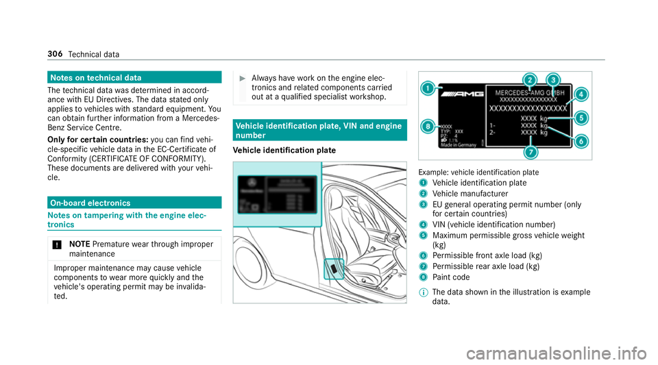
Ve hicle identification plate Example:
vehicle identification plate
1 Vehicle identification plate
2 Vehicle manufacturer
3 EUgeneral operating pe rmit number (only
fo r cer tain countries)
4 VIN (vehicle identification number)
5 Maximum permissible gross vehicle weight
(kg)
6 Perm issible front axle load (kg)
7 Perm issible rear axle load (kg)
8 Paint code
% The data shown in the illustration is example
data. 306
Tech nical da ta
Page 310 of 409
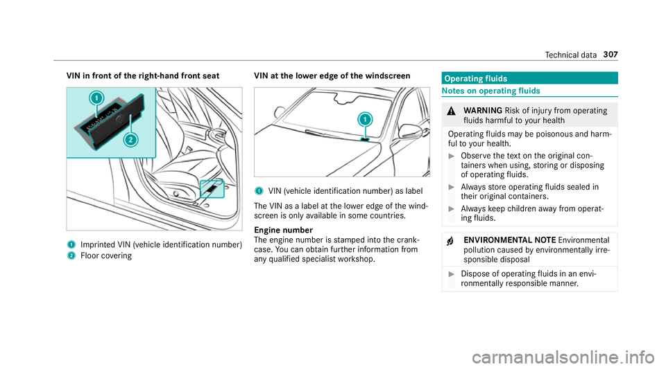
VIN in front of the
right-hand front seat 1
Imprinted VIN (vehicle identification number)
2 Floor co vering VIN at the lo
wer edge of the windscreen 1
VIN (vehicle identi fication number) as label
The VIN as a label at the lo wer edge of the wind‐
screen is only available in some countries.
Engine number
The engine number is stamped into the crank‐
case. You can obtain fur ther information from
any qualified specialist workshop. Operating
fluids Note
s on operating fluids &
WARNING Risk of inju ryfrom operating
fl uids harmful to your health
Operating fluids may be poisonous and harm‐
ful to yo ur health. #
Obser vethete xt on the original con‐
ta iners when using, storing or disposing
of operating fluids. #
Alw aysst ore operating fluids sealed in
th eir original conta iners. #
Alw ayske ep children away from operat‐
ing fluids. +
ENVIRONMEN
TALNO TEEnvironmental
pollution caused byenvironmen tally ir re‐
sponsible disposal #
Dispose of operating fluids in an envi‐
ro nmentally responsible manner. Te
ch nical da ta307