2018 MERCEDES-BENZ AMG GT COUPE reset
[x] Cancel search: resetPage 25 of 465

&
WARNING Risk of accident due tocon‐
necting devices tothe diagnostics con‐
nection
If yo u connect equipment toa diagnostics
connection in theve hicle, it may af fect the
operation of vehicle sy stems.
As a result, the operating saf ety of theve hi‐
cle could be af fected. #
Only connect equipment toa diagnos‐
tics connection in theve hicle which is
appr ovedfo ryo ur vehicle byMercedes-
Benz. &
WARNING Risk of accident due to
objects in the driver's foot we ll
Objects in the driver's foot we ll may impede
pedal tr avel or block a depressed pedal.
This jeopardises the operating and road
saf ety of theve hicle. #
Stow all objects in theve hicle securely
so that they cannot getinto the driver's
fo ot we ll. #
Alw aysfit th efloor mats securely and
as prescribed in order toensure that
th ere is alw ays suf ficient room forthe
pedals. #
Do not use loose floor mats and do not
place floor mats on top of one ano ther. *
NO
TEBattery discharging from using
devices connected tothe diagnostics
connection Using devices at
the diagnostics connection
drains the batter y. #
Check thech arge leve l of the batter y. #
Ifth ech arge leve l is lo w,charge the
batter y,e.g. bydriving a considerable
dis tance. Connecting equipment
tothe diagnostics con‐
nection can lead toemissions monitoring infor‐
mation being reset, forex ample. This may lead
to theve hicle failing tomeet therequ irements of
th e next emissions inspection during the main
inspection. Qualified specialist
workshop
A qu alified specialist workshop has the neces‐
sary special skills, tools and qualifications to
cor rectly car ryout any necessary workon your
ve hicle. This particularly applies tosaf ety-re le‐
va nt wo rks.
Alw ays ha vethefo llowing workcar ried out on
yo ur vehicle at a qualified specialist workshop:
R safety-re leva nt wo rks
R service and maintenance work
R repair work
R modifications as well as ins tallations and
con versions
R workon electronic components
Mercedes‑AMG recommends a Mercedes‑Benz
service centre. Ve
hicle registration
Mercedes-Benz may ask its service centres to
car ryout tech nical inspections on cer tain vehi‐
cles. The quality or saf ety of theve hicle is
impr oved as a result of the inspection. 22
General no tes
Page 27 of 465

of an accident,
rescue services can use the QR
code toquickly find the appropriate rescue card
fo ryo ur vehicle. The cur rent rescue card con‐
ta ins the most impor tant information about your
ve hicle in a compact form , e.g. thero uting of the
electric lines.
Fu rther information can be obtained at http://
www.mercedes-benz.de/qr-code. Data
storage Electronic control units
Elect
ronic control units are fitted in your vehicle.
Some of these are necessary forth e safe opera‐
tion of your vehicle, while some assist you when
driving (driver assis tance sy stems). In addition,
yo ur vehicle pr ovides com fort and enter tainment
functions, which are also made possible byelec‐
tronic control units.
Elect ronic control units contain da tamemories
which can temp orarily or permanently store
te ch nical information about theve hicle's operat‐
ing state, component loads, main tenance
re qu irements and tech nical events or faults. In
general, this information documents thest ate
of a component part, a module, a sy stem or the
sur roundings such as:
R operating status of sy stem components (e.g.
fi ll le vels, battery status, tyre pressure)
R status messages concerning theve hicle or
its individual components (e.g. number of
wheel revo lutions/speed, longitudinal accel‐
eration, lateral acceleration, display of fas‐
te ned seat belts)
R malfunctions or faults in impor tant sy stem
components (e.g. lights, brakes)
R information on events leading tovehicle
damage
R system reactions in special driving situations
(e.g. airbag deployment, inter vention of sta‐
bility control sy stems)
R ambient conditions (e.g. temp erature, rain
sensor)
In addition toprov iding the actual control unit
function, this data assists the manufacturer in
de tecting and rectifying faults and optimising
ve hicle functions. The majority of this data is te
mp orary and is only processed in theve hicle
itself. Only a small portion of the data is stored
in theeve nt or fault memor y.
When your vehicle is serviced, tech nical da ta
from theve hicle can be read out byservice net‐
wo rkemplo yees (e.g. workshops, manufactur‐
ers) or third parties (e.g. breakdown services).
Services include repair services, maintenance
processes, warranty claims and quality assur‐
ance measures, forex ample. The read out is per‐
fo rm ed via the legally prescribed port forthe
diagnostics connection in theve hicle. The
re spective service network locations or third
parties collect, process and use the data. They
document tech nical statuses of theve hicle,
assist in finding faults and impr oving quality and
are transmitted tothe manufacturer, if neces‐
sar y.Fu rthermore, the manufacturer is subject
to product liability. Forth is, the manufacturer
requ irestech nical da tafrom vehicles.
Fa ult memories in theve hicle can be reset by a
service outlet as part of repair or maintenance
wo rk. 24
General no tes
Page 70 of 465
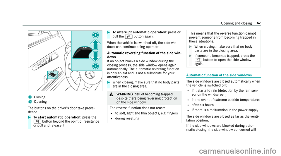
1
Closing
2 Opening
The but tons on the driver's door take prece‐
dence. #
Tostart automatic operation: pressthe
W button be yond the point of resis tance
or pull and release it. #
Tointer rupt automatic operation: press or
pull theW button again.
When theve hicle is switched off, the side win‐
do ws can continue being ope rated.
Au tomatic reve rsing function of the side win‐
do ws
If an object bloc ksa side wind owduring the
closing process, the side window opens again
automaticall y.The automatic reve rsing function
is only an aid and is not a substitute foryo ur
attentiveness. #
When closing, make sure that no body parts
are in the closing area. &
WARNING Risk of becoming trapped
despi tethere being reve rsing pr otection
on the side window
The reve rse function does not react:
R tosoft, light and thin objects, e.g. fingers
R during resetting This means
that there ve rse function cann ot
pr eve nt someone from becoming trapped in
th ese situations. #
When closing, make sure that no body
parts are in the closing area. #
If someone becomes trapped, press the
W button toopen the side window
again. Au
tomatic function of the side windo ws The side windo
wsare closed automatically when
th eve hicle is switched off:
R if it starts torain (de tection bythera in sen‐
sor on the windscreen)
R intheeve nt of extreme outside temp eratures
R afte r six hours
R ifth ere is a malfunction in the po wer supp ly
The side windo wsare closed as far as theve nti‐
lation position.
If th e side windo wsare bloc ked during auto‐
matic closing, the side window concerned will Opening and closing
67
Page 72 of 465
Problems with
the side windo ws Problem
Possible causes/consequences and M
MSolutions
A side window cann otbe closed and
yo u cannot see the cause. #
Check tosee whe ther any objects are in the window guide.
& WARNING Risk of becoming trapped or fata lly injured if reve rsing pr otection is not activated
If yo u close a side wind owagain immediately af ter it has been bloc ked or reset, the side window closes
with increased or maximum forc e. The reve rsing feature is then not active.
Pa rts of the body could become trapped in the closing area in the process. #
Make sure that no parts of the body are in the closing area. #
Tostop the closing process, release the button or press the button again toreopen the side win‐
do w. If a side window is obstructed during closing and
reopens again slightly: #
Immediately af terth e window is bloc ked, pull the cor responding switch again until the side window has
closed, and hold the switch for an additional second.
The side window will be closed with increased forc e.
If a side window is obstructed again during closing and reopens again slightly: #
Repeat the pr evious step.
The side window is closed without the automatic reve rsing function. Opening and closing
69
Page 87 of 465
#
When leaving theve hicle, alw aysta ke
th eke y with you and lock theve hicle.
This also applies tothe digital vehicle
ke y if the "Digital Vehicle Key" function
is activated via Mercedes me connect. The memory function can be used when
the igni‐
tion is switched off.
St oring
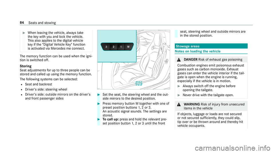
Seat adjustments for up tothre e people can be
st ored and called up using the memory function.
The following sy stems can be selected:
R Seat and backrest
R Driver's side: steering wheel
R Driver's side: outside mir rors on the driver's
and front passenger sides #
Set the seat, thesteering wheel and the out‐
side mir rors to the desired position. #
Press memory button M toge ther with one of
preset position buttons 1,2 or 3.
An acou stic signal sounds. The settings are
st ored. #
Tocall up: press and hold there leva nt pre‐
set position button 1,2 or 3 until the front seat,
steering wheel and outside mir rors are
in thestored position. St
ow age areas Note
s on loading theve hicle &
DANG ER Risk of exhaust gas poisoning
Combustion engines emit poisonous exhaust
ga ses such as carbon monoxide. Exhaust
ga ses can enter theve hicle interior if theta il‐
gate is open when the engine is running,
especially if theve hicle is in motion. #
Alw ays switch off the engine before
opening theta ilgate. #
Never drive with theta ilgate open. &
WARNING Risk of inju ryfrom unsecu red
items in theve hicle
If objects, luggage or loads are not secured
or not secured suf ficientl y,they could slip,
tip ove r or be throw n around and thereby hit
ve hicle occupants. 84
Seats and stowing
Page 103 of 465
&
WARNING Risk of accident due tomis‐
judgement of dis tances when using the
outside mir ror
The outside mir rors reflect objects on a
smaller scale. The objects in view are in fact
closer than they appear.
As a result, you may misjud gethe dis tance
between you and thero ad user driving
behind you, e.g. when changing lanes. #
Therefore, alw ays look over your shoul‐
der in order toensure that you are
aw are of the actual dis tance between
yo u and thero ad users driving behind
yo u. Fo
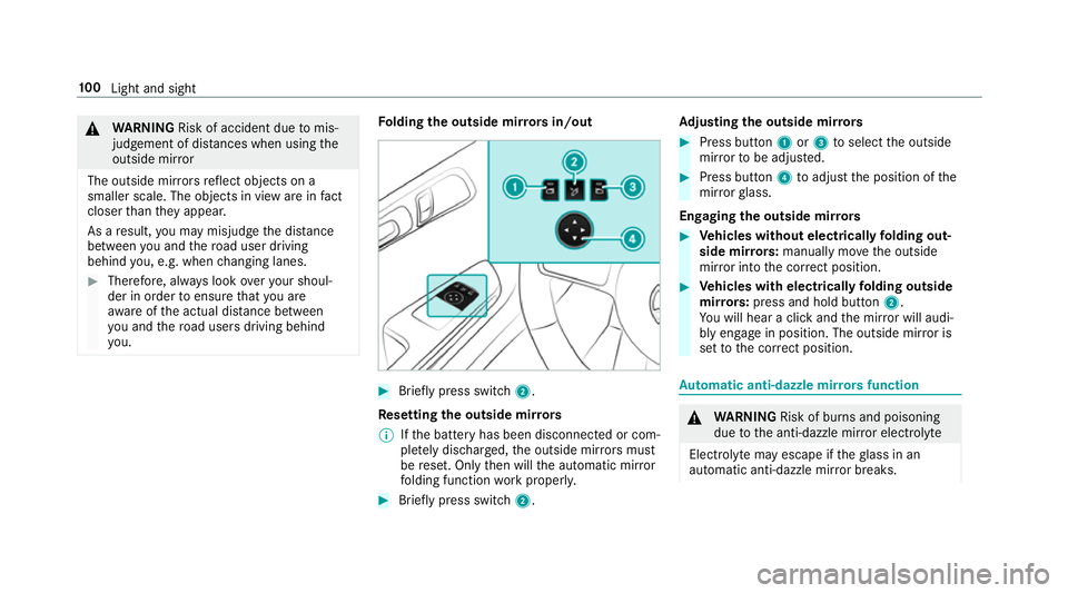
lding the outside mir rors in/out #
Brief lypress switch 2.
Re setting the outside mir rors
% Ifth e battery has been disconnected or com‐
ple tely discharged, the outside mir rors must
be reset. Only then will the automatic mir ror
fo lding function workproperly. #
Brief lypress switch 2. Ad
justing the outside mir rors #
Press button 1or3 toselect the outside
mir rorto be adjus ted. #
Press button 4toadjust the position of the
mir rorgl ass.
Engaging the outside mir rors #
Vehicles without electrical lyfolding out‐
side mir rors:manually mo vethe outside
mir ror into the cor rect position. #
Vehicles with electrical lyfolding outside
mir rors: press and hold button 2.
Yo u will hear a click and the mir ror will audi‐
bly engage in position. The outside mir ror is
set tothe cor rect position. Au
tomatic anti-dazzle mir rors function &
WARNING Risk of bu rns and poisoning
due tothe anti-dazzle mir ror electrolyte
Electrolyte may escape if theglass in an
automatic anti-dazzle mir ror breaks. 100
Light and sight
Page 152 of 465
%
Inthis phase you can adjust RACE START
depending on thero ad conditions: you can
va ry the engine speed bypulling on one of
th esteering wheel gearshift paddles. The
segments in the multifunction display flic ker
ra pidly.
% Ifth e brake pedal is not released af ter a
short while, RACE START is cancelled. The
RACE START cancelled messageappears in
th e multifunction displa y.#
Take your foot off the brake, but keep the
accelerator pedal depressed.
The vehicle pulls away at maximum accelera‐
tion. The RACE START active message
appears in the multifunction displa y.
RACE START is deacti vated when theve hicle rea‐
ch es a speed of appr oximately 50 km/h.
RACE START is deacti vated immediately if you
re lease the accelerator pedal during RACE
ST ART or if any of the activation conditions are
no longer fulfilled. The RACE START cancelled
message appears in the multifunction displa y.%
After using it se veral times in short succes‐
sion, RACE START is una vailable until a cer‐
ta in dis tance has been driven. Fu
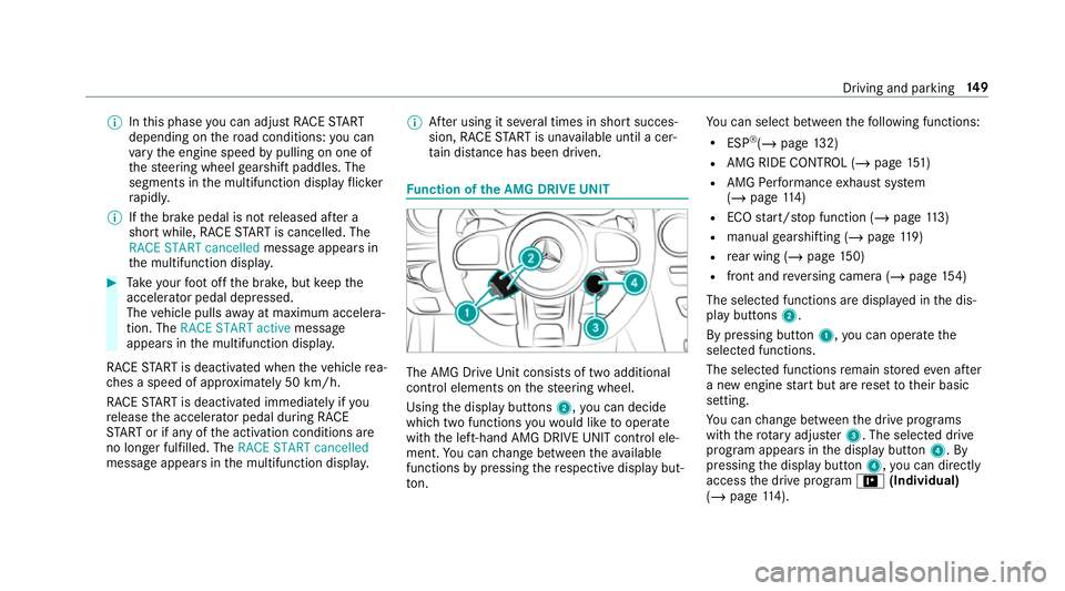
nction of the AMG DRIVE UNIT The AMG Drive
Unit consists of two additional
control elements on thesteering wheel.
Using the display buttons 2,you can decide
which two functions youwo uld like tooperate
with the left-hand AMG DRIVE UNIT control ele‐
ment. You can change between theav ailable
functions bypressing there spective display but‐
to n. Yo
u can select between thefo llowing functions:
R ESP ®
(/ page 132)
R AMG RIDE CONTROL (/ page151)
R AMG Performance exhaust sy stem
(/ page 114)
R ECO start/ stop function (/ page113)
R manual gearshifting (/ page119)
R rear wing (/ page150)
R fron t and reve rsing camera (/ page154)
The sele cted functions are displ ayed in the dis‐
play buttons 2.
By pressing button 1,you can operate the
selected functions.
The selected functions remain stored even af ter
a new engine start but are reset totheir basic
setting.
Yo u can change between the drive prog rams
with thero tary adjus ter3. The selected drive
program appears in the display button 4. By
pressing the display button 4,you can direct ly
access the drive program =(Individual)
(/ page 114). Driving and pa
rking 14 9
Page 172 of 465
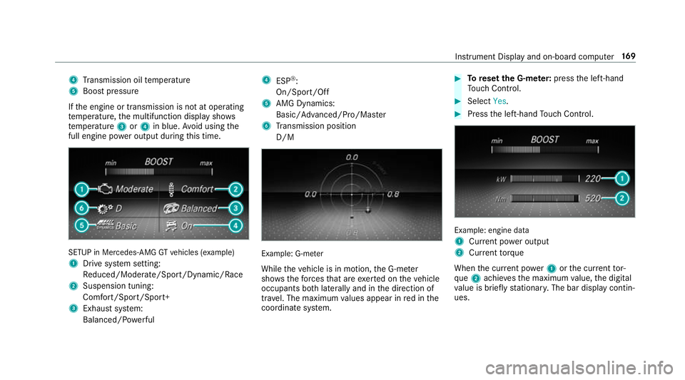
4
Transmission oil temp erature
5 Boost pressure
If th e engine or transmission is not at operating
te mp erature, the multifunction display sho ws
te mp erature 3or4 in blue. Avoid using the
full engine po wer output during this time. SETUP in Mercedes
-AMG GTvehicles (e xample)
1 Drive sy stem setting:
Re duced/Moderate/Spo rt/Dynamic/Race
2 Suspension tuning:
Comfort/Sport/Sport+
3 Exhau stsystem:
Balanced/ Powe rful 4
ESP®
:
On/Sport/Off
5 AMG Dynamics:
Basic/ Advanced/Pro/Ma ster
6 Transmission position
D/M Example: G-m
eter
While theve hicle is in motion, the G-me ter
sho wsthefo rc es that are exerted on theve hicle
occupants bo thlaterally and in the direction of
tra vel. The maximum values appear in red in the
coordinate sy stem. #
Toreset the G-m eter: press the left-hand
To uch Control. #
Select Yes. #
Press the left-hand Touch Control. Example: engine data
1
Current po wer output
2 Curr enttorque
When the cur rent po wer1 orthe cur rent tor‐
qu e2 achie vesth e maximum value, the digital
va lue is brief lystationar y.The bar display contin‐
ues. Instrument Display and on-board computer
16 9