2018 MERCEDES-BENZ AMG GT COUPE seats
[x] Cancel search: seatsPage 90 of 294

Exterior mirror pushed out of position
If an exterior mirror has been pushed out of
position, proceed as follows:
XPress and hold button?until you hear a click
and the mirror engages audibly into position
(
Ypage 87).
The mirror housing is engaged again and you
can adjust the exterior mirrors as usual
(
Ypage 87).
Automatic anti-glare mirrors
GWARNING
Electrolyte may escape if the glass in an auto-
matic anti-glare mirror breaks. The electrolyte
is harmful and causes irritation. It must not
come into contact with your skin, eyes, res-
piratory organs or clothing or be swallowed.
There is a risk of injury.
If you come into contact with the electrolyte,
observe the following:
RRinse off the electrolyte from your skin
immediately with water.
RImmediately rinse the electrolyte out of
your eyes thoroughly with clean water.
RIf the electrolyte is swallowed, immediately
rinse your mouth out thoroughly. Do not
induce vomiting.
RIf electrolyte comes into contact with your
skin or hair or is swallowed, seek medical
attention immediately.
RImmediately change out of clothing which
has come into contact with electrolyte.
RIf an allergic reaction occurs, seek medical
attention immediately.
The rear-view mirror and the exterior mirror on
the driver's side automatically go into anti-glare
mode if the following conditions are met simul-
taneously:
Rthe ignition is switched on
Rincident light from headlamps strikes the sen-
sor in the rear-view mirror
The mirrors do not go into anti-glare mode if
reverse gear is engaged or if the interior lighting is switched on.
Parking position for the exterior mir-
ror on the front-passenger side
Storing the parking position
You can position the front-passenger side exte- rior mirror in such a way that you can see the
rear wheel on that side as soon as you engage
reverse gear. You can store this position.
Using reverse gear
:Memory button M
;Button for the driver's side exterior mirror
=Button for the front-passenger side exterior
mirror
?Switch
XSelect key position 2with the Start/Stop
button.
XPress button =.
XStart the engine.
XEngage reverse gear.
The exterior mirror on the front-passenger
side moves to the default setting parking posi-
tion.
XUse button ?to adjust the exterior mirror to
a position that allows you to see the rear
wheel and the curb.
The parking position is stored.
iIf you shift the transmission to another posi-
tion, the exterior mirror on the front-
passenger side returns to the driving position
after approximately ten seconds.
Using the memory button
You can store the parking position of the exte-
rior mirror on the front-passenger side using
memory button M:. The reverse gear must not
be engaged.
88Mirrors
Seats, steering wheel and mirrors
Page 91 of 294

XSelect key position2with the Start/Stop
button.
XPress button =.
XUse button?to adjust the exterior mirror to
a position that allows you to see the rear
wheel and the curb.
XPress memory button M: and one of the
arrows on button ?within three seconds.
The parking position is stored if the exterior
mirror does not move.
XIf the mirror moves out of position, repeat the
steps.
Calling up a stored parking position set-
ting
XSelect key position 2with the Start/Stop
button.
XAdjust the exterior mirror on the front-
passenger side using button =.
XStart the engine.
XEngage reverse gear.
The exterior mirror on the front-passenger
side moves to the stored parking position.
The exterior mirror on the front-passenger side
moves back to its original position:
Ras soon as you exceed a speed of 9 mph
(15 km/h)
Rabout ten seconds after you have disengaged
reverse gear
Rif you press button ;for the exterior mirror
on the driver's side
Memory function
Important safety notes
GWARNING
If you use the memory function on the driver's side while driving, you could lose control of
the vehicle as a result of the adjustments
being made. There is a risk of an accident.
Only use the memory function on the driver's
side when the vehicle is stationary.
GWARNING
When the memory function adjusts the seat or steering wheel, you and other vehicle occu-
pants – particularly children – could become
trapped. There is a risk of injury.
While the memory function is making adjust-
ments, make sure that no one has any body
parts in the sweep of the seat or steering
wheel. If somebody becomes trapped, imme-diately release the memory function position
button. The adjustment process is stopped.
GWARNING
Children could become trapped if they acti-
vate the memory function, particularly when
unattended. There is a risk of injury.
When leaving the vehicle, always take the
SmartKey with you and lock the vehicle. Never
leave children unsupervised in the vehicle.
The memory function can be used at any time,
even if the ignition is switched off.
Storing settings
With the memory function, you can store up to
three different settings, e.g. for three different
people.
The following settings are stored as a single
memory preset:
Rseat and backrest position
Rdriver's side: position of the exterior mirrors
on the driver's and front-passenger sides
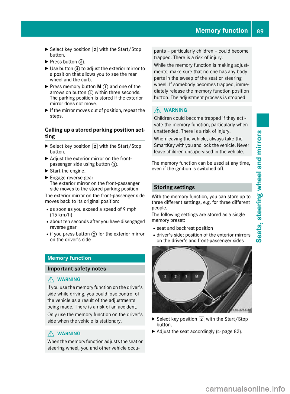
XSelect key position 2with the Start/Stop
button.
XAdjust the seat accordingly (Ypage 82).
Memory function89
Seats, steering wheel and mirrors
Z
Page 92 of 294

XOn the driver's side, adjust the steering wheel(Ypage 85) and the exterior mirrors
(Ypage 87).
XPress memory button Mand one of the stor-
age position buttons 1,2or 3within three
seconds.
The settings are stored in the selected preset
position. A tone sounds when the settings
have been completed.
Calling up a stored setting
XPress and hold the corresponding storage
position button 1,2or 3until:
RSeat
RSteering wheel
RExterior mirrors
are in the stored position.
iThe steering wheel and seat adjustment
procedure is interrupted as soon as you
release the storage position button. Exterior
mirror adjustment continues.
90Memory function
Seats, steering wheel and mirrors
Page 146 of 294

If there is an obstacle within this range, the rel-
evant warning displays light up and a warning
tone sounds. If the distance falls below the min-
imum, the distance may no longer be shown.
Warning displays
:Segments on the left-hand side of the vehi-
cle
;Segments on the right-hand side of the vehi-
cle
=Segments showing operational readiness
The warning displays show the distance
between the sensors and the obstacle. The
warning display for the front area is in the instru-
ment cluster. The warning display for the rear
area is located on the cover behind the seats in
the rear compartment.
The warning display for each side of the vehicle
is divided into five yellow and two red segments.
Parking Assist PARKTRONIC is operational if
operational readiness indicator =lights up.
The selected transmission position and the
direction in which the vehicle is rolling deter-
mine which warning display is active when the
engine is running.
Transmission posi-
tionWarning display
hFront area activated
k, ior the vehicle
is rolling backwardsRear and front areas
activated
jNo areas activated
One or more segments light up as the vehicle
approaches a detected obstacle, depending on
the vehicle's distance from the obstacle:
From the:
Rsixth segment onwards, you will hear an inter-
mittent warning tone for approximately two
seconds.
Rseventh segment onwards, you will hear a
warning tone for approximately two seconds.
This indicates that you have now reached the minimum distance.
Deactivating or activating Parking
Assist PARKTRONIC
:Indicator lamp
;Deactivates or activates Parking Assist
PARKTRONIC
If indicator lamp :lights up, Parking Assist
PARKTRONIC is deactivated.
iParking Assist PARKTRONIC is automati-
cally activated when you set the Start/Stop
button to key position 2.
144Driving systems
Driving and parking
Page 269 of 294

sizes and corresponding pressures for tires
mounted at the factory.
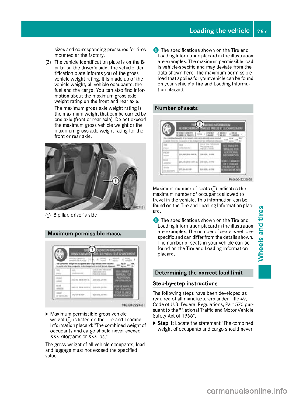
(2) The vehicle identification plate is on the B- pillar on the driver's side. The vehicle iden-
tification plate informs you of the gross
vehicle weight rating. It is made up of the
vehicle weight, all vehicle occupants, the
fuel and the cargo. You can also find infor-
mation about the maximum gross axle
weight rating on the front and rear axle.
The maximum gross axle weight rating is
the maximum weight that can be carried by
one axle (front or rear axle). Do not exceed
the maximum gross vehicle weight or the
maximum gross axle weight rating for the
front or rear axle.
:B-pillar, driver's side
Maximum permissible mass.
XMaximum permissible gross vehicle
weight :is listed on the Tire and Loading
Information placard: "The combined weight of occupants and cargo should never exceed
XXX kilograms or XXX lbs."
The gross weight of all vehicle occupants, load
and luggage must not exceed the specified
value.
iThe specifications shown on the Tire and
Loading Information placard in the illustration
are examples. The maximum permissible load
is vehicle-specific and may deviate from the
data shown here. The maximum permissible
load that applies for your vehicle can be found
on your vehicle's Tire and Loading Informa-
tion placard.
Number of seats
Maximum number of seats :indicates the
maximum number of occupants allowed to
travel in the vehicle. This information can be
found on the Tire and Loading Information plac-
ard.
iThe specifications shown on the Tire and
Loading Information placard in the illustration
are examples. The number of seats is vehicle-
specific and can differ from the details shown.
The number of seats in your vehicle can be
found on the Tire and Loading Information
placard.
Determining the correct load limit
Step-by-step instructions
The following steps have been developed as
required of all manufacturers under Title 49,
Code of U.S. Federal Regulations, Part 575 pur-
suant to the "National Traffic and Motor Vehicle
Safety Act of 1966".
XStep 1: Locate the statement "The combined
weight of occupants and cargo should never
Loading the vehicle267
Wheels and tires
Z
Page 278 of 294

Weight of optional extras
The combined weight of those optional extras
that weigh more than the replaced standard
parts and more than 5 lbs (2.3 kg). These
optional extras, such as high-performance
brakes, level control, a roof rack or a high-volt-
age battery, are not included in the curb weight
and the weight of the accessories.
TIN (Tire Identification Number)
This is a unique identifier which can be used by
a tire manufacturer to identify tires, for example
for a product recall, and thus identify the pur-
chasers. The TIN is made up of the manufactur- er's identity code, tire size, tire type code and
the manufacturing date.
Load bearing index
The load bearing index (also load index) is a code
that contains the maximum load bearing capa-
city of a tire.
Traction
Traction is the result of friction between the tires
and the road surface.
Treadwear indicators
Narrow bars (tread wear bars) that are distrib-
uted over the tire tread. If the tire tread is level
with the bars, the wear limit of áin (1.6 mm)
has been reached.
Occupant distribution
The distribution of occupants in a vehicle at their
designated seating positions.
Total load limit
Nominal load and luggage load plus 68 kg
(150 lbs) multiplied by the number of seats in
the vehicle.
Changing a wheel
Flat tire
The "Breakdown assistance" section
(Ypage 246) contains information and notes on
how to deal with a flat tire.
Rotating the wheels
GWARNING
Interchanging the front and rear wheels may
severely impair the driving characteristics if
the wheels or tires have different dimensions. The wheel brakes or suspension components
may also be damaged. There is a risk of acci-
dent.
Rotate front and rear wheels only if the wheels and tires are of the same dimensions.
!On vehicles equipped with a tire pressure
monitor, electronic components are located
in the wheel.
Tire-mounting tools should not be used near
the valve. This could damage the electronic
components.
Only have tires changed at a qualified spe-
cialist workshop.
Always observe the instructions and safety
notes in the "Mounting a wheel" section
(
Ypage 277).
The wear patterns on the front and rear tires
differ, depending on the operating conditions.
Rotate the wheels before a clear wear pattern
has formed on the tires. Front tires typically
wear more on the shoulders and the rear tires in
the center.
On vehicles that have the same size front and
rear wheels, you can rotate the wheels accord-
ing to the intervals in the tire manufacturer's
warranty book in your vehicle documents. If no
warranty book is available, the tires should be
rotated every 3,000 to 6,000 miles (5,000 to
10,000 km). Depending on tire wear, this may
be required earlier. Do not change the direction
of wheel rotation.
Clean the contact surfaces of the wheel and the
brake disc thoroughly every time a wheel is rota- ted. Check the tire pressure and reactivate the
tire pressure monitor if necessary.
Direction of rotation
Tires with a specified direction of rotation have
additional benefits, e.g. if there is a risk of hydro-planing. These advantages can only be gained if
the tires are installed corresponding to the
direction of rotation.
276Changing a wheel
Wheels and tires