2018 MERCEDES-BENZ AMG GT COUPE ignition
[x] Cancel search: ignitionPage 254 of 294
!Avoid repeated and lengthy starting attempts. Otherwise, the catalytic converter could be
damaged by the non-combusted fuel.
XDo not start the vehicle using a rapid charging device.
If your vehicle's battery is discharged, the engine can be jump-started from another vehicle or
from a donor battery using jumper cables.
The battery is not accessible in all vehicles. If the other vehicle's battery is not accessible, jump-start
the vehicle using a donor battery or a jump-starting device.
Observe the following during the jump-starting procedure:
Rthe jumper cables must not come into contact with parts that can move when the engine is
running, such as the V-belt pulley or the fan.
Rnon-insulated parts of the terminal clamps must not come into contact with other metal parts
while the jumper cables are connected to the battery and the jump-starting connection point.
Ronly use jumper cables that are not damaged and have a sufficient cross-section and insulated
terminal clamps.
Rjump-starting may be performed only using batteries with a nominal voltage of 12 V.
Ryou may only jump-start the vehicle when the engine and exhaust system are cold.
Rthe vehicles must not touch each other.
RIf the battery is fully discharged, leave the battery that is being used to jump-start connected for
a few minutes before attempting to start. This charges the battery slightly.
XSecure the vehicle by applying the electric parking brake.
XShift the transmission to position j.
XMake sure the ignition and all electrical consumers are switched off.
All indicator lamps in the instrument cluster must be off. When using the SmartKey, turn the
SmartKey to positionuin the ignition lock and remove it (
Ypage 106).
XOpen the hood.
iRight-hand-drive vehicle: the jump-starting connection points may be located on the other
side of the vehicle.
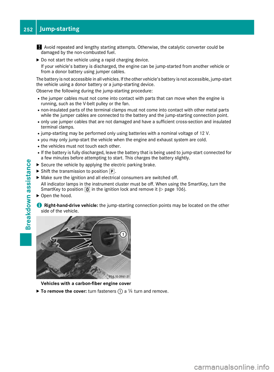
Vehicles with a carbon-fiber engine cover
XTo remove the cover: turn fasteners:aÕ turn and remove.
252Jump-starting
Breakdown assistance
Page 256 of 294
Towing and tow-starting
Important safety notes
GWARNING
The rear axle locks when:
Rthe engine is not running
Rthe engine stalls while the vehicle is being
towed
Rthere is a malfunction in the power supply
or the vehicle's electrical system
There is a risk of an accident.
In the event of a breakdown, you should
always have the vehicle transported.
GWARNING
If the brake system or power steering is mal-
functioning and your vehicle is then towed
away, significantly more effort may be
required to steer and brake than is normally
required. There is a risk of an accident.
In such cases, use a tow bar. Before towing,
make sure that the steering moves freely.
GWARNING
When towing or tow-starting another vehicle
and its weight is greater than the permissible
gross weight of your vehicle, the:
Rthe towing eye could detach itself
Rthe vehicle/trailer combination could roll-
over.
There is a risk of an accident.
When towing or tow-starting another vehicle,
its weight should not be greater than the per- missible gross weight of your vehicle.
Details on the permissible gross vehicle weight
of your vehicle can be found on the vehicle iden-
tification plate (
Ypage 282).
!Use the SmartKey instead of the Start/Stop
button when towing the vehicle.
Start the engine and keep it running. The
SmartKey is in position 2in the ignition lock.
Set the transmission to iusing the E-
SELECT selector lever. Make sure that you
then leave the SmartKey in position 2.Check the transmission position in the instru-
ment cluster.
!Make sure that the electric parking brake is
released. If the electric parking brake is faulty,
visit a qualified specialist workshop.
!Secure the tow rope or tow bar to the towing
eye only. Otherwise, the vehicle could
become damaged.
!When Active Brake Assist, Distance Pilot
DISTR ONIC or the HOLD function is activated,
the vehicle brakes automatically in certain
situations.
To avoid damage to the vehicle, deactivate
these systems in the following or similar sit-
uations:
Rwhen towing the vehicle
Rin the car wash
!Do not use the towing eyes for recovery pur-
poses as this could damage the vehicle. If in
doubt, recover the vehicle with a crane.
!When towing, pull away slowly and
smoothly. If the tractive power is too high, the
vehicles could be damaged.
!Shift the automatic transmission to position
i and do not open the driver's or front-
passenger door when towing the vehicle
away. Otherwise, the automatic transmission
may shift to position jwhich can cause
damage to both vehicles.
!Do not tow with sling-type equipment. This
could damage the vehicle.
!The vehicle can be towed a maximum of
30 miles (50km). The towing speed of 30 mph
(50 km/h) must not be exceeded.
If the vehicle has to be towed more than
30 miles (50km), the entire vehicle must be
raised and transported.
!Observe the transmission fluid temperature
(AMG menu) in the on-board computer when
towing. The transmission fluid temperature
must not exceed 250 ‡ (
120 †). If this
occurs, you must stop towing immediately.
!Tow-starting the vehicle is not permitted.
The transmission may otherwise be damaged.
254Towing and tow-starting
Breakdown assistance
Page 257 of 294
Also observe the following notes:
RIf the engine does not start, try jump-starting
it (Ypage 251). Tow-starting the vehicle is not
permitted.
RIf it is not possible to jump-start the vehicle,
have it transported to the nearest qualified
specialist workshop, e.g. an authorized
Mercedes-Benz Center.
If the vehicle can no longer be driven because of
an accident or breakdown, you have the follow-
ing options:
Rtransporting the vehicle
As a rule, you should have the vehicle trans-
ported.
Rtowing the vehicle with a tow rope or tow bar
Only tow the vehicle in exceptional cases. The
engine must be running if you tow the vehicle
with a tow rope or tow bar.
If the vehicle has suffered transmission damage,
have it transported on a transporter or trailer.
Observe the display messages in the instrument
cluster.
The battery must be connected and charged.
Otherwise, you:
Rwill not be able to switch on the ignition with
the Start/Stop button
Rcannot start the engine
Rcannot release the electric parking brake
Rcannot shift the automatic transmission to
position i
Disarm the automatic locking feature before the
vehicle is towed (
Ypage 72). You could other-
wise be locked out when pushing or towing the
ve
hicle.
Installing/removing the towing eye
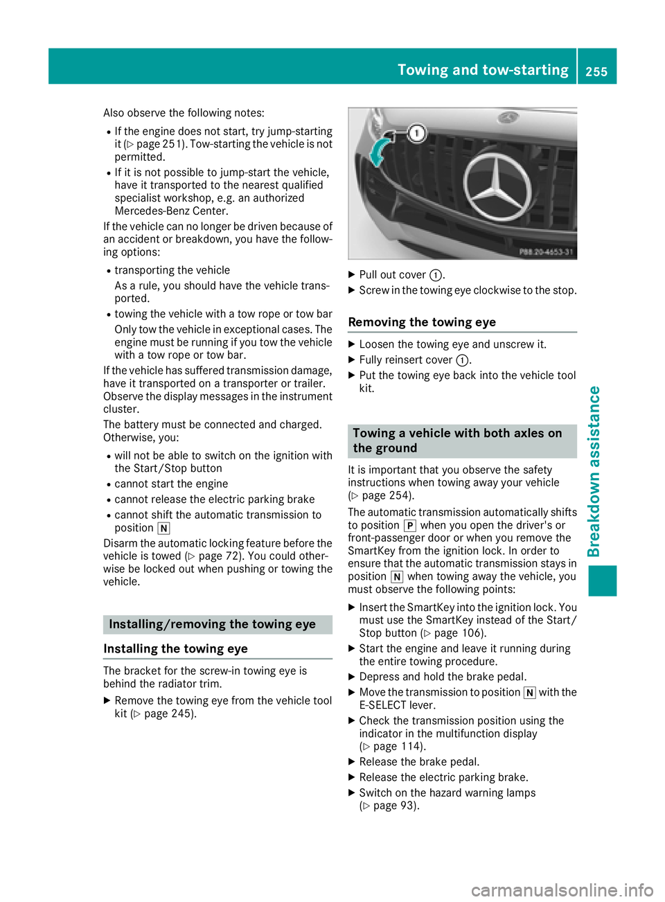
Installing the towing eye
The bracket for the screw-in towing eye is
behind the radiator trim.
XRemove the towing eye from the vehicle tool
kit (Ypage 245).
XPull out cover :.
XScrew in the towing eye clockwise to the stop.
Removing the towing eye
XLoosen the towing eye and unscrew it.
XFully reinsert cover :.
XPut the towing eye back into the vehicle tool
kit.
Towing a vehicle with both axles on
the ground
It is important that you observe the safety
instructions when towing away your vehicle
(
Ypage 254).
The automatic transmission automatically shifts
to position jwhen you open the driver's or
front-passenger door or when you remove the
SmartKey from the ignition lock. In order to
ensure that the automatic transmission stays in
position iwhen towing away the vehicle, you
must observe the following points:
XInsert the SmartKey into the ignition lock. You
must use the SmartKey instead of the Start/
Stop button (
Ypage 106).
XStart the engine and leave it running during
the entire towing procedure.
XDepress and hold the brake pedal.
XMove the transmission to position iwith the
E-SELECT lever.
XCheck the transmission position using the
indicator in the multifunction display
(
Ypage 114).
XRelease the brake pedal.
XRelease the electric parking brake.
XSwitch on the hazard warning lamps
(Ypage 93).
Towing and tow-starting255
Breakdo wn assis tance
Z
Page 258 of 294
In order to signal a change of direction when
towing the vehicle with the hazard warning
lamps switched on, use the combination switch
as usual. In this case, only the indicator lamps
for the direction of travel flash. After resetting
the combination switch, the hazard warning
lamp starts flashing again.
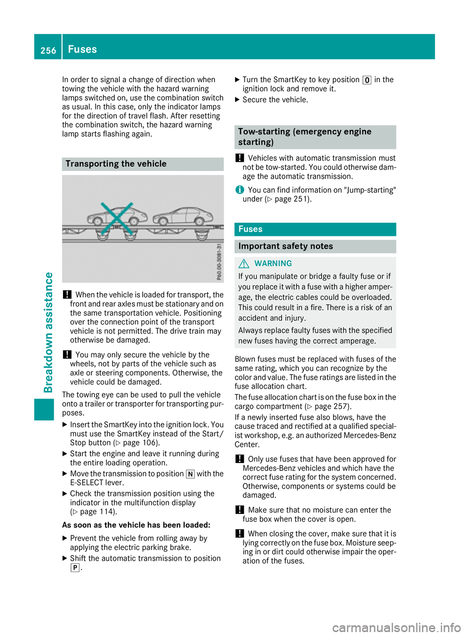
Transporting the vehicle
!When the vehicle is loaded for transport, the
front and rear axles must be stationary and on the same transportation vehicle. Positioning
over the connection point of the transport
vehicle is not permitted. The drive train may
otherwise be damaged.
!You may only secure the vehicle by the
wheels, not by parts of the vehicle such as
axle or steering components. Otherwise, the
vehicle could be damaged.
The towing eye can be used to pull the vehicle
onto a trailer or transporter for transporting pur- poses.
XInsert the SmartKey into the ignition lock. You
must use the SmartKey instead of the Start/
Stop button (
Ypage 106).
XStart the engine and leave it running during
the entire loading operation.
XMove the transmission to position iwith the
E-SELECT lever.
XCheck the transmission position using the
indicator in the multifunction display
(
Ypage 114).
As soon as the vehicle has been loaded:
XPrevent the vehicle from rolling away by
applying the electric parking brake.
XShift the automatic transmission to position
j.
XTurn the SmartKey to key position uin the
ignition lock and remove it.
XSecure the vehicle.
Tow-starting (emergency engine
starting)
!
Vehicles with automatic transmission must
not be tow-started. You could otherwise dam-
age the automatic transmission.
iYou can find information on "Jump-starting"
under (Ypage 251).
Fuses
Important safety notes
GWARNING
If you manipulate or bridge a faulty fuse or if
you replace it with a fuse with a higher amper- age, the electric cables could be overloaded.
This could result in a fire. There is a risk of an
accident and injury.
Always replace faulty fuses with the specified
new fuses having the correct amperage.
Blown fuses must be replaced with fuses of the
same rating, which you can recognize by the
color and value. The fuse ratings are listed in the
fuse allocation chart.
The fuse allocation chart is on the fuse box in the
cargo compartment (
Ypage 257).
If a newly inserted fuse also blows, have the
cause traced and rectified at a qualified special-
ist workshop, e.g. an authorized Mercedes-Benz Center.
!Only use fuses that have been approved for
Mercedes-Benz vehicles and which have the
correct fuse rating for the system concerned.
Otherwise, components or systems could be
damaged.
!Make sure that no moisture can enter the
fuse box when the cover is open.
!When closing the cover, make sure that it is
lying correctly on the fuse box. Moisture seep-
ing in or dirt could otherwise impair the oper-
ation of the fuses.
256Fuses
Breakdown assistance
Page 259 of 294
The fuses in your vehicle serve to close down
faulty circuits. If a fuse blows, all the compo-
nents on the circuit and their functions stop
operating.
Before changing a fuse
XSwitch off the engine.
XSwitch off all electrical consumers.
XOpen the driver's door.
The on-board electronics are now in key posi-
tionu. This is the same as the key having
been removed.
or, if the SmartKey is inserted in the ignition
lock:
XRemove the SmartKey from the ignition lock.
XSecure the vehicle against rolling away
(Ypage 122).
All indicator lamps in the instrument cluster
must be off.
Fuse box in the front-passenger foot-
well
!
The floor panel must be installed properly,
otherwise moisture or dirt could impair the
function of the fuses.
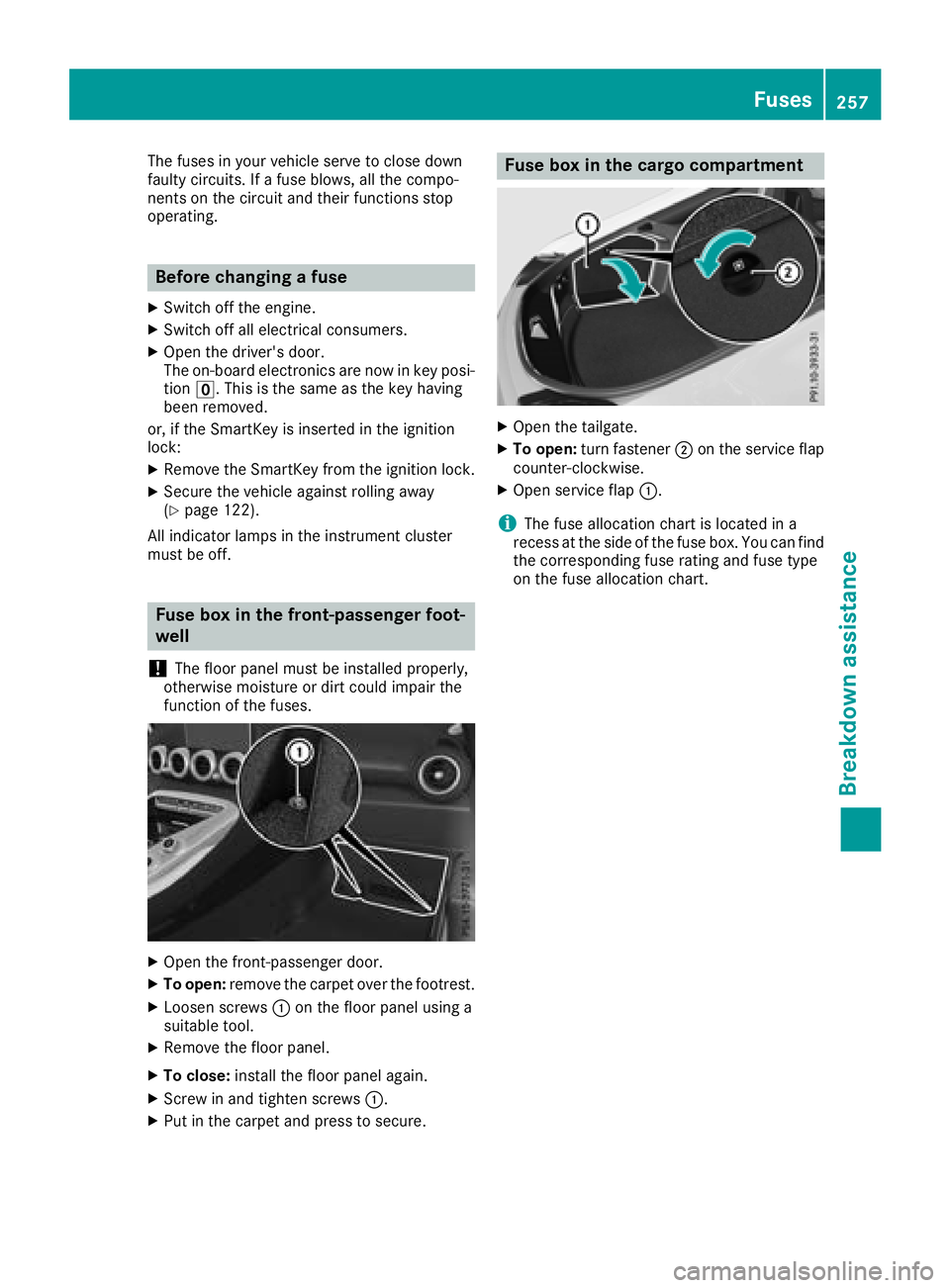
XOpen the front-passenger door.
XTo open: remove the carpet over the footrest.
XLoosen screws :on the floor panel using a
suitable tool.
XRemove the floor panel.
XTo close: install the floor panel again.
XScrew in and tighten screws :.
XPut in the carpet and press to secure.
Fuse box in the cargo compartment
XOpen the tailgate.
XTo open:turn fastener ;on the service flap
counter-clockwise.
XOpen service flap :.
iThe fuse allocation chart is located in a
recess at the side of the fuse box. You can find
the corresponding fuse rating and fuse type
on the fuse allocation chart.
Fuses257
Breakdown assistance
Z
Page 267 of 294
ensure that the replacement or alternate Tires
and wheels allow the TPMS to continue to
function properly.
It is the driver's responsibility to set the tire
pressure to that recommended for cold tires
which is suitable for the operating situation
(
Ypage 261). Note that the correct tire pressure
for the current operating situation must first be
taught-in to the tire pressure monitor. If a sub-
stantial loss of pressure occurs, the warning
threshold for the warning message is aligned to
the taught-in reference values. Restart the tire
pressure monitor after adjusting the pressure of
the cold tires (
Ypage 266). The current pres-
sures are saved as new reference values. As a
result, a warning message will appear if the tire pressure drops significantly.
The tire pressure monitor does not warn you of
an incorrectly set tire pressure. Observe the
notes on the recommended tire pressure
(
Ypage 261).
The tire pressure monitor is not able to warn you
of a sudden loss of pressure, e.g. if the tire is
penetrated by a foreign object. In the event of a
sudden loss of pressure, bring the vehicle to a
halt by braking carefully. Avoid abrupt steering
movements.
The tire pressure monitor has a yellow warning
lamp in the instrument cluster for indicating
pressure loss or a malfunction. Whether the
warning lamp flashes or lights up indicates
whether a tire pressure is too low or the tire
pressure monitor is malfunctioning:
Rif the warning lamp is lit continuously, the tire
pressure on one or more tires is significantly
too low. The tire pressure monitor is not mal-
functioning.
Rif the warning lamp flashes for around a
minute and then remains lit constantly, the
tire pressure monitor is malfunctioning.
In addition to the warning lamp, a message
appears in the multifunction display. Observe
the information on display messages
(
Ypage 186).
It may take up to ten minutes for a malfunction
of the tire pressure monitor to be indicated. A
malfunction will be indicated by the tire pres-
sure warning lamp flashin
g for approximately
one minute and then remaining lit. When the
malfunction has been rectified, the tire pressure
warning lamp goes out after a few minutes of
driving. The tire pressure values indicated by the on-
board computer may differ from those meas-
ured at a gas station with a pressure gage. The
tire pressures shown by the on-board computer
refer to those measured at sea level. At high
altitudes, the tire pressure values indicated by a pressure gage are higher than those shown by
the on-board computer. In this case, do not
reduce the tire pressures.
The operation of the tire pressure monitor can
be affected by interference from radio transmit-
ting equipment (e.g. radio headphones, two-way
radios) that may be being operated in or near the vehicle.
Checking the tire pressure electroni-
cally
XSwitch on the ignition (Ypage 106).
XPress òon the steering wheel to call up
the list of menus.
XPress 9or: on the steering wheel to
select the Servicemenu.
XPressa.
XPress9or: to select Tire Pres‐sure.
XPressa.
The current tire pressure of each tire is shown
in the multifunction display.
If the vehicle was parked for longer than
20 minutes, the Tire pressure will be
displayed after driving a few minutesmessage appears.
After a teach-in process, the tire pressure mon-
itor automatically detects new wheels or new
sensors. As long as a clear allocation of the tire
pressure value to the individual wheels is not
possible, theTire
PressureMonitorActivemessage is shown instead of the tire pressure
display. The tire pressures are already being
monitored.
Tire pressure monitor warning mes-
sages
If the tire pressure monitor detects a pressure
loss in one or more tires, a warning message is
shown in the multifunction display. The yellow
tire pressure warning lamp then lights up.
RIf thePlease Correct Tire Pressuremessage appears in the multifunction display,
the tire pressure in at least one tire is too low.
Tire pressure265
Wheels and tires
Z
Page 268 of 294
The tire pressure must be corrected when the
opportunity arises.
RIf theCheck Tiresmessage appears in the
multifunction display, the tire pressure in at
least one tire has dropped significantly. The
tires must be checked.
RIf the WarningTireMalfunctionmessage
appears in the multifunction display, the tire
pressure in at least one tire has dropped sud-
denly. The tires must be checked.
Observe the instructions and safety notes in the
display messages in the "Tires" section
(
Ypage 186).
If the wheel positions on the vehicle are rotated,
the tire pressures may be displayed for the
wrong positions for a short time. This is rectified after a few minutes of driving, and the tire pres-
sures are displayed for the correct positions.
Restarting the tire pressure monitor
When you restart the tire pressure monitor, all
existing warning messages are deleted and the
warning lamps go out. The monitor uses the cur-
rently set tire pressures as the reference valuesfor monitoring. In most cases, the tire pressure
monitor will automatically detect the new refer-
ence values after you have changed the tire
pressure. However, you can also set reference
values manually as described here. The tire
pressure monitor then monitors the new tire
pressure values.
XSet the tire pressure to the value recommen-
ded for the corresponding driving situation on
the Tire and Loading Information placard on
the driver's side B-pillar (
Ypage 261).
You can find more tire pressure values for
various operating conditions in the tire pres-
sure table inside the fuel filler flap
(
Ypage 261).
XMake sure that the tire pressure is correct on
all four wheels.
XSwitch on the ignition (Ypage 106).
XPress òon the steering wheel to call up
the list of menus.
XPress 9or: on the steering wheel to
select the Servicemenu.
XPressa.
XPress9or: to select Tire Pres‐sure.
XPressa.
The current tire pressure for each wheel or
the Tire pressure will be displayed
after driving a few minutesmessage
will be displayed in the multifunction display.
XPress :.
The UseCurrentPressuresasNewRef‐erenceValuesmessage appears in the mul-
tifunction display.
If you wish to confirm the restart:
XPress a.
The TirePress.MonitorRestartedmes-
sage appears on the multifunction display.
After driving for a few minutes, the system
checks whether the current tire pressures are
within the specified range. The new tire pres-
sures are then accepted as reference values
and monitored.
If you wish to cancel the restart:
XPress %.
The tire pressure values stored at the last
restart will continue to be monitored.
Loading the vehicle
Instruction labels for tires and loads
GWARNING
Overloaded tires can overheat, causing a
blowout. Overloaded tires can also impair the steering and driving characteristics and lead
to brake failure. There is a risk of accident.
Observe the load rating of the tires. The load
rating must be at least half of the GAWR of
your vehicle. Never overload the tires by
exceeding the maximum load.
Two instruction labels on your vehicle show the maximum possible load.
(1) The Tire and Loading Information placard is on the B-pillar on the driver's side. The Tire
and Loading Information placard shows the
permissible number of vehicle occupants
and the maximum permissible load of the
vehicle. It also contains details of the tire
266Loading the vehicle
Wheels and tires
Page 279 of 294
An arrow on the sidewall of the tire indicates its
correct direction of rotation.
Storing wheels
Store wheels that are not being used in a cool,
dry and preferably dark place. Protect the tires
from oil, grease, gasoline and diesel.
Mounting a wheel
Preparing the vehicle
XStop the vehicle on solid, non-slippery and
level ground.
XApply the electric parking brake manually.
XBring the front wheels into the straight-ahead position.
XShift the transmission to position j.
XSwitch off the engine.
XWith KEYLESS-GO start function or vehi-
cles with KEYLESS-GO:open the driver's
door.
The vehicle electronics are now in key posi-
tion u. This is the same as the SmartKey
having been removed.
or
XRemove the SmartKey from the ignition lock.
XIf included in the vehicle equipment, remove
the tire-change tool kit from the vehicle.
XSafeguard the vehicle against rolling away.
Securing the vehicle to prevent it from
rolling away
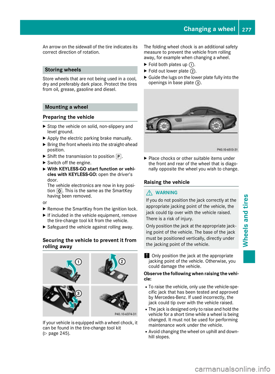
If your vehicle is equipped with a wheel chock, it
can be found in the tire-change tool kit
(
Ypage 245). The folding wheel chock is an additional safety
measure to prevent the vehicle from rolling
away, for example when changing a wheel.
XFold both plates up
:.
XFold out lower plate ;.
XGuide the lugs on the lower plate fully into the
openings in base plate =.
XPlace chocks or other suitable items under
the front and rear of the wheel that is diago-
nally opposite the wheel you wish to change.
Raising the vehicle
GWARNING
If you do not position the jack correctly at the
appropriate jacking point of the vehicle, the
jack could tip over with the vehicle raised.
There is a risk of injury.
Only position the jack at the appropriate jack-
ing point of the vehicle. The base of the jack
must be positioned vertically, directly under
the jacking point of the vehicle.
!Only position the jack at the appropriate
jacking point of the vehicle. Otherwise, you
could damage the vehicle.
Observe the following when raising the vehi-
cle:
RTo raise the vehicle, only use the vehicle-spe-
cific jack that has been tested and approved
by Mercedes-Benz. If used incorrectly, the
jack could tip over with the vehicle raised.
RThe jack is designed only to raise and hold the
vehicle for a short time while a wheel is being
changed. It must not be used for performing
maintenance work under the vehicle.
RAvoid changing the wheel on uphill and down- hill slopes.
Changing a wheel277
Wheels and tires
Z