2018 LINCOLN CONTINENTAL fuse
[x] Cancel search: fusePage 7 of 615

360 Degree Camera..................................234
Cruise Control
Principle of Operation................................237
Using Cruise Control..................................237
Using Adaptive Cruise Control................238
Driving Aids
Driver Alert....................................................246
Lane Keeping System................................247
Blind Spot Information System................253
Cross Traffic Alert........................................255
Steering.........................................................259
Pre-Collision Assist.....................................260
Drive Control................................................264
Load Carrying
Load Limit......................................................266
Towing
Towing a Trailer.............................................271
Recommended Towing Weights.............272
Essential Towing Checks...........................273
Towing the Vehicle on Four Wheels......275
Driving Hints
Breaking-In....................................................276
Economical Driving.....................................276
Driving Through Water...............................276
Floor Mats......................................................277
Roadside Emergencies
Roadside Assistance..................................279
Hazard Flashers..........................................280
Fuel Shutoff..................................................280
Jump Starting the Vehicle..........................281
Post-Crash Alert System...........................284
Transporting the Vehicle...........................285
Customer Assistance
Getting the Services You Need...............286
In California (U.S. Only)..............................287
The Better Business Bureau (BBB) AutoLine Program (U.S. Only).......................288
Utilizing the Mediation/Arbitration Program(Canada Only)..........................................289
Getting Assistance Outside the U.S. andCanada......................................................290
Ordering Additional Owner's Literature......................................................................292
Reporting Safety Defects (U.S. Only)......292
Reporting Safety Defects (Canada Only)......................................................................293
Fuses
Fuse Specification Chart...........................294
Changing a Fuse.........................................309
Maintenance
General Information.....................................312
Opening and Closing the Hood...............312
Under Hood Overview - 3.0L....................313
Under Hood Overview - 2.7L EcoBoost™/3.7L..............................................................315
Engine Oil Dipstick - 2.7L EcoBoost™/3.0LEcoBoost™..................................................317
Engine Oil Dipstick - 3.7L............................317
Engine Oil Check..........................................317
Oil Change Indicator Reset.......................318
Engine Coolant Check................................319
4
Continental (CPL) Canada/United States of America, enUSA, Edition date: 201706, Second-Printing
Table of Contents
Page 11 of 615

Anti-lock braking system
Avoid smoking, flames or sparks
Battery
Battery acid
Brake fluid - non petroleum based
Brake system
Brake system
Cabin air filter
Check fuel cap
Child safety door lock or unlock
Child seat lower anchor
Child seat tether anchor
Cruise control
Do not open when hot
Engine air filter
Engine coolant
Engine coolant temperature
Engine oil
Explosive gas
Fan warning
Fasten seatbelt
Flammable
Front airbag
Front fog lamps
Fuel pump reset
Fuse compartment
Hazard flashers
Heated rear window
8
Continental (CPL) Canada/United States of America, enUSA, Edition date: 201706, Second-Printing
Introduction E270480 E71340 E71880 E231160 E67017
Page 56 of 615

WARNING: Do not attempt to service,repair, or modify the seat airbagsupplemental restraint systems, its fuses orthe seat cover on a vehicle containing seatairbags as you could be seriously injured orkilled. Contact your authorized dealer assoon as possible.
WARNING: If the side airbag hasdeployed, the airbag will not function again.The side airbag system (including the seat)must be inspected as soon as possible. If theairbag is not replaced, the unrepaired areawill increase the risk of injury in a crash.
The side airbags are on the outboard sideof the seatbacks of the front seats. Theairbag was designed to inflate between thedoor panel and occupant to further enhancethe protection provided to occupants incertain side impact crashes.
The system consists of the following:
•A label or embossed side panelindicating that side airbags are fitted toyour vehicle.
•Side airbags inside the driver and frontpassenger seatbacks.
•Front passenger sensing system.
Crash sensors and monitoringsystem with readiness indicator.See Crash Sensors and AirbagIndicator (page 55).
The design and development of the sideairbag system included recommendedtesting procedures that were developed bya group of automotive safety experts knownas the Side Airbag Technical Working Group.These recommended testing procedureshelp reduce the risk of injuries related to thedeployment of side airbags.
DRIVER AND PASSENGER KNEE
AIRBAGS
Driver and passenger knee airbags arelocated under or within the instrument panel.During a crash, the restraints control modulemay activate the driver and passenger kneeairbags (individually or both) based on crashseverity and respective occupant conditions.Under certain crash and occupant conditions,the driver and passenger knee airbags maydeploy (individually or both) but thecorresponding front airbag may not activate.As with front and side airbags, it is importantto be properly seated and restrained toreduce the risk of death or serious injury.
53
Continental (CPL) Canada/United States of America, enUSA, Edition date: 201706, Second-Printing
Supplementary Restraints SystemE152533 E67017
Page 178 of 615

12 Volt DC Power Point
WARNING: Do not plug optionalelectrical accessories into the cigar lightersocket. Incorrect use of the cigar lighter cancause damage not covered by the vehiclewarranty, and can result in fire or seriousinjury.
Note:When you switch the ignition on, youcan use the socket to power 12 voltappliances with a maximum current ratingof 15 amps.
If the power supply does not work after youswitch the ignition off, switch the ignition on.Note:Do not hang any accessory from theaccessory plug.
Note:Do not use the power point over thevehicle capacity of 12 volt DC 180 watts ora fuse may blow.
Note:Always keep the power point capsclosed when not in use.
Do not insert objects other than an accessoryplug into the power point. This damages thepower point and may blow the fuse.
Run the vehicle for full capacity use of thepower point.
To prevent the battery from running out ofcharge:
•Do not use the power point longer thannecessary when the vehicle is notrunning.
•Do not leave devices plugged inovernight or when you park your vehiclefor extended periods.
Locations
Power points may be in the followinglocations:
•On the instrument panel.
•Inside the center console.
•On the rear of the center console.
110 Volt AC Power Point (If Equipped)
WARNING: Do not keep electricaldevices plugged in the power pointwhenever the device is not in use. Do notuse any extension cord with the 110 volt ACpower point, since it will defeat the safetyprotection design. Doing so may cause thepower point to overload due to poweringmultiple devices that can reach beyond the150 watt load limit and could result in fire orserious injury.
Note:The power point turns off when youswitch the ignition off, or when the batteryvoltage drops below 11 volts.
You can use the power point for electricdevices that require up to 150 watts. It is onthe rear of the center console.
175
Continental (CPL) Canada/United States of America, enUSA, Edition date: 201706, Second-Printing
Auxiliary Power Points
Page 188 of 615

Note:If your vehicle is on a steep slope,more fuel may be required.
Filling a Portable Fuel Container
WARNING: Flow of fuel through a fuelpump nozzle can produce static electricity.This can cause a fire if you are filling anungrounded fuel container.
Use the following guidelines to avoidelectrostatic charge build-up, which canproduce a spark, when filling an ungroundedfuel container:
•Only use an approved fuel container totransfer fuel to your vehicle. Place thecontainer on the ground when filling it.
•Do not fill a fuel container when it isinside your vehicle (including the cargoarea).
•Keep the fuel pump nozzle in contactwith the fuel container when filling it.
•Do not use a device that holds the fuelpump nozzle lever in the fill position.
Adding Fuel From a Portable FuelContainer
WARNING: Do not insert the nozzle ofa fuel container or an aftermarket funnel intothe fuel filler neck. This may damage the fuelsystem filler neck or its seal and cause fuelto run onto the ground.
WARNING: Do not try to pry open orpush open the capless fuel system withforeign objects. This could damage the fuelsystem and its seal and cause injury to youor others.
WARNING: Do not dispose of fuel inthe household refuse or the public sewagesystem. Use an authorized waste disposalfacility.
When refueling the vehicle fuel tank from afuel container, use the fuel filler funnelincluded with your vehicle. See Fuel FillerFunnel Location (page 184).
Note:Do not use aftermarket funnels as theymay not work with the capless fuel systemand can damage it.
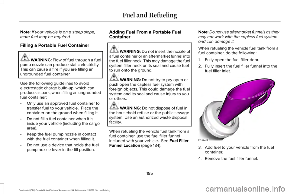
When refueling the vehicle fuel tank from afuel container, do the following:
1. Fully open the fuel filler door.
2. Fully insert the fuel filler funnel into thefuel filler inlet.
3. Add fuel to your vehicle from the fuelcontainer.
4. Remove the fuel filler funnel.
185
Continental (CPL) Canada/United States of America, enUSA, Edition date: 201706, Second-Printing
Fuel and RefuelingE157452
Page 274 of 615

TOWING A TRAILER
WARNING: Do not exceed theGVWR or the GAWR specified on thecertification label.
WARNING: Towing trailers beyondthe maximum recommended grosstrailer weight exceeds the limit of yourvehicle and could result in enginedamage, transmission damage,structural damage, loss of vehiclecontrol, vehicle rollover and personalinjury.
Note:There may be electrical itemssuch as fuses or relays that can affecttrailer towing operation. See Fuses(page 294).
The load capacity of your vehicle isdesignated by weight not volume. Youmay not necessarily be able to use allavailable space when loading yourvehicle or trailer.
Towing a trailer places extra load on theengine, transmission, axle, brakes, tires,and suspension. Inspect thesecomponents before, during and aftertowing.
Load Placement
To help minimize how trailer movementaffects the vehicle when driving:
•Load the heaviest items closest tothe trailer floor.
•Load the heaviest items in the centerof the left and right side trailer tires.
•Load the heaviest items above thetrailer axles or just slightly forwardtoward the trailer tongue. Do notallow the final trailer tongue weightto go above or below 10-15% of theloaded trailer weight.
•Select a ball mount with the correctrise or drop. When both the loadedvehicle and trailer are connected, thetrailer frame should be level, orslightly angled down toward thevehicle, when viewed from the side.
When driving with a trailer or payload, aslight takeoff vibration or shudder maybe present due to the increased payloadweight. Additional information regardingproper trailer loading and setting yourvehicle up for towing is located in theLoad Carrying chapter. See Load Limit(page 266).
You can also find information in the RV& Trailer Towing Guide available at yourauthorized dealer, or online.
271
Continental (CPL) Canada/United States of America, enUSA, Edition date: 201706, Second-Printing
Towing
Page 285 of 615

Note:Do not disconnect the battery of thedisabled vehicle as this could damage thevehicle electrical system.
Park the booster vehicle close to the hoodof the disabled vehicle, making sure the twovehicles do not touch.
Connecting the Jumper Cables
WARNING: Do not attach the cablesto fuel lines, engine rocker covers, the intakemanifold or electrical components asgrounding points. Stay clear of moving parts.To avoid reverse polarity connections, makesure that you correctly identify the positive(+) and negative (-) terminals on both thedisabled and booster vehicles beforeconnecting the cables.
WARNING: Do not attach the end ofthe positive cable to the studs or L-shapedeyelet located above the positive (+) terminalof your vehicle’s battery. High current mayflow through and cause damage to the fuses.
WARNING: Do not connect the end ofthe second cable to the negative (-) terminalof the battery to be jumped. A spark maycause an explosion of the gases thatsurround the battery.
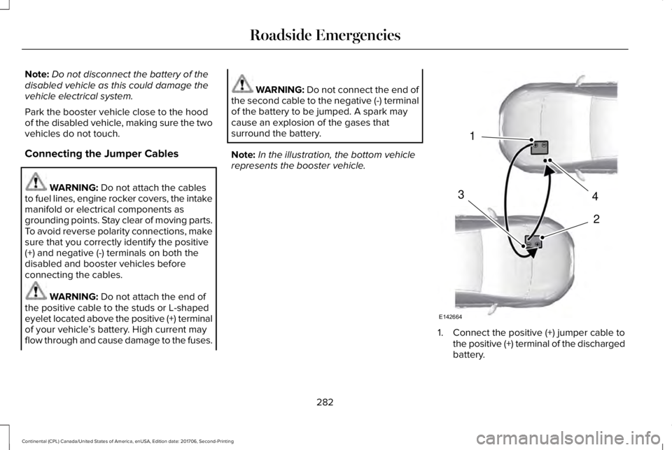
Note:In the illustration, the bottom vehiclerepresents the booster vehicle.
1. Connect the positive (+) jumper cable tothe positive (+) terminal of the dischargedbattery.
282
Continental (CPL) Canada/United States of America, enUSA, Edition date: 201706, Second-Printing
Roadside Emergencies4
2
1
3
E142664
Page 297 of 615

FUSE SPECIFICATION CHART
Power Distribution Box
WARNING: Always disconnect thebattery before servicing high current fuses.
WARNING: To reduce risk of electricalshock, always replace the cover to the powerdistribution box before reconnecting thebattery or refilling fluid reservoirs.
The power distribution box is in the enginecompartment. It has high-current fuses thatprotect your vehicle's main electrical systemsfrom overloads.
If the battery has been disconnected andreconnected, some features will need to bereset. See Changing the 12V Battery (page325).
294
Continental (CPL) Canada/United States of America, enUSA, Edition date: 201706, Second-Printing
Fuses