Page 447 of 523

7-35
7
Maintenance
By jump starting
After a jump start from a good bat-
tery, drive the vehicle for 20-30 min-
utes before it is shutoff. The vehicle
may not restart if you shut it off
before the battery had a chance to
adequately recharge. See “Jump
Starting” in chapter 6 for more infor-
mation on jump starting procedures.Information An inappropriately disposedbattery can be harmful to
the environment and human
health.
Dispose of the battery according to
your local law(s) or regulations.
Reset items
The following items may need to be
reset after the battery has been dis-
charged or the battery has been dis-connected.
Auto up/down window
Sunroof
Trip computer
Climate control system
Driver position memory system
Clock
Audio system
i
AGM battery (if equipped)
Absorbent Glass Matt (AGM) batteries are maintenance-free and we recommend that
the AGM battery be serviced
by an authorized HYUNDAI
dealer. For charging your
AGM battery, use only fully
automatic battery chargers
that are specially developed
for AGM batteries.
When replacing the AGM bat-
tery, we recommend that you
use parts for replacement
from an authorized HYUNDAI
dealer.
Do not open or remove the
cap on top of the battery. This
may cause leaks of internal
electrolyte that could result in
severe injury.
CAUTION
Page 448 of 523

7-36
MaintenanceT
T IIRR EESS AA NN DD WW HHEEEELLSS
Tire care
For proper maintenance, safety, and
maximum fuel economy, you must
always maintain recommended tire
inflation pressures and stay within the
load limits and weight distribution rec-
ommended for your vehicle.
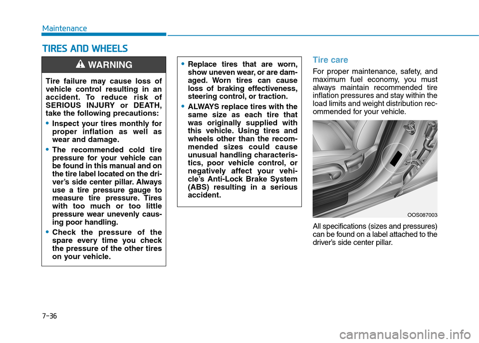
All specifications (sizes and pressures)
can be found on a label attached to the
driver’s side center pillar.Replace tires that are worn,
show uneven wear, or are dam-
aged. Worn tires can cause
loss of braking effectiveness,
steering control, or traction.
ALWAYS replace tires with the
same size as each tire that
was originally supplied with
this vehicle. Using tires andwheels other than the recom-
mended sizes could cause
unusual handling characteris-
tics, poor vehicle control, or
negatively affect your vehi-
cle’s Anti-Lock Brake System(ABS) resulting in a seriousaccident.
Tire failure may cause loss of
vehicle control resulting in an
accident. To reduce risk of
SERIOUS INJURY or DEATH,
take the following precautions:
Inspect your tires monthly for
proper inflation as well as
wear and damage.
The recommended cold tire
pressure for your vehicle can
be found in this manual and onthe tire label located on the dri-
ver’s side center pillar. Always
use a tire pressure gauge to
measure tire pressure. Tires
with too much or too little
pressure wear unevenly caus-ing poor handling.
Check the pressure of the
spare every time you checkthe pressure of the other tires
on your vehicle.
WARNING
OOS087003
Page 452 of 523

7-40
Maintenance
Tire replacement
If the tire is worn evenly, a tread wear indicator will appear as a solid band
across the tread. This shows there isless than 1.6 mm (1/16 in.) of tread
left on the tire. Replace the tire when
this happens.
Do not wait for the band to appear
across the entire tread before replac-
ing the tire.
OLMB073027
Tread wear indicatorTo reduce the risk of DEATH or
SERIOUS INJURY:
Replace tires that are worn,
show uneven wear, or are
damaged. Worn tires can
cause loss of braking effec-
tiveness, steering control, andtraction.
Always replace tires with the
same size as each tire that
was originally supplied with
this vehicle. Using tires andwheels other than the recom-
mended sizes could cause
unusual handling characteris-
tics, poor vehicle control, or
negatively affect your vehi-
cle’s Anti-Lock Brake System(ABS) resulting in a seriousaccident.
WARNING When replacing tires (or
wheels), it is recommended to
replace the two front or two
rear tires (or wheels) as a pair.Replacing just one tire can
seriously affect your vehicle’s
handling. If only replacing one
pair of tires, it is recommend-
ed to install the pair of new
tires on the rear axle.
Tires degrade over time, even
when they are not being used.
Regardless of the remaining
tread, HYUNDAI recommendsthat tires be replaced after six
(6) years of normal service.
Heat caused by hot climates or frequent high loading condi-
tions can accelerate the aging
process. Failure to follow this
warning may cause sudden
tire failure, which could lead to
a loss of vehicle control result-ing in an accident.
Page 470 of 523
7-58
Maintenance
Engine compartment fuse panel
TypeFuse NameSymbolFuse RatingCircuit Protected
FUSE
TCMT115ATCM
V/PUMPVACUUMPUMP20AVacuum Pump
F/PUMPFUEL
PUMP20AE/R Junction Block (RLY.7)
BATT1140AIGPM ((Fuse - F21, F24, F28, F33), Leak Current Autocut Device)
DCT1DCT
140ATCM
DCT2DCT
240ATCM
4WD20A4WD ECM
ABS1140AESC Control Module, Multifunction Switch
ABS2230AESC Control Module
Page 471 of 523
7-59
7
Maintenance
Fuse NameSymbolFuse RatingCircuit Protected
SENSOR2S210APCB Block (A/CON Relay), E/R Junction Block (RLY.9), Purge Control Solenoid Valve,
RCV Control Solenoid Valve, Oil Control Valve #1~#2
ECU2E210AECM
ECU1E120AECM
INJECTORINJECTOR15A-
SENSOR1S115AOxygen Sensor (Up), Oxygen Sensor (Down)
IGN COILIGN COIL20AIgnition Coil #1~#4
ECU3E315AECM
A/CON10APCB Block (A/CON Relay)
ECU5E510AECM
SENSOR4S415AVacuum Pump
ABS3310AESC Control Module, Multipurpose Check Connector
TCM2T215ATCM, Transaxle Range Switch
Engine compartment fuse panel
■ Gamma 1.6 T-GDI
Page 473 of 523
7-61
7
Maintenance
Fuse NameSymbolFuse RatingCircuit Protected
IGN COILIGN COIL20AIgnition Coil #1~#3
ECU3E315AECM
A/CON10APCB Block (A/CON Relay)
ECU5E510AECM
SENSOR4S415A-
ABS3310AMultipurpose Check Connector, ESC Control Module
TCM2T215A-
SENSOR3S310AE/R Junction Block (RLY.7)
ECU4E415AECM
H/LAMP10APCB Block (Head Lamp (High) Relay)
HORN15APCB Block (Horn Relay)
Page 477 of 523
![Hyundai Kona 2018 Owners Manual 7-65
7
Maintenance
[1] : High beam, [2] : Low beam
Headlamp and position lamp
1. Open the hood.
2. Disconnect the negative batterycable.
3. Remove the bulb cover by turning it counterclockwise.
4. Di Hyundai Kona 2018 Owners Manual 7-65
7
Maintenance
[1] : High beam, [2] : Low beam
Headlamp and position lamp
1. Open the hood.
2. Disconnect the negative batterycable.
3. Remove the bulb cover by turning it counterclockwise.
4. Di](/manual-img/35/16231/w960_16231-476.png)
7-65
7
Maintenance
[1] : High beam, [2] : Low beam
Headlamp and position lamp
1. Open the hood.
2. Disconnect the negative batterycable.
3. Remove the bulb cover by turning it counterclockwise.
4. Disconnect the bulb socket-con- nector. (for low beam and high beam)
5. Remove the bulb from the head- lamp assembly.
6. Install a new bulb.
7. Connect the bulb socket-connec- tor. (for low beam and high beam)
8. Install the bulb cover by turning it clockwise.
Turn signal lamp
1. Open the hood.
2. Disconnect the negative batterycable.
3.Remove the socket (1) from the assembly by turning the socket
counterclockwise until the tabs on
the socket align with the slots on
the assembly.
4.Remove the bulb from the socket by pressing it in and rotating it
counterclockwise until the tabs on
the bulb align with the slots in the
socket. Pull the bulb out of the
socket. 5.Insert a new bulb by inserting it into
the socket and rotating it until it
locks into place.
6.Install the socket in the assembly by aligning the tabs on the socket
with the slots in the assembly.
7.Push the socket into the assembly and turn the socket clockwise.
Daytime running light
If the LED lamp does not operate, we
recommend you to have the vehicle
checked by an authorized HYUNDAI
dealer.OOS077038OOS077034
Page 479 of 523

7-67
7
Maintenance
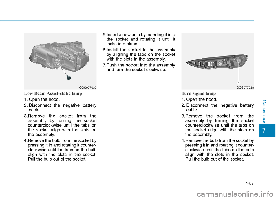
Low Beam Assist-static lamp
1. Open the hood.
2. Disconnect the negative batterycable.
3.Remove the socket from the assembly by turning the socket
counterclockwise until the tabs on
the socket align with the slots on
the assembly.
4.Remove the bulb from the socket by pressing it in and rotating it counter-
clockwise until the tabs on the bulb
align with the slots in the socket.
Pull the bulb out of the socket. 5.Insert a new bulb by inserting it into
the socket and rotating it until it
locks into place.
6.Install the socket in the assembly by aligning the tabs on the socket
with the slots in the assembly.
7.Push the socket into the assembly and turn the socket clockwise.
Turn signal lamp
1. Open the hood.
2. Disconnect the negative battery cable.
3.Remove the socket from the assembly by turning the socket
counterclockwise until the tabs on
the socket align with the slots on
the assembly.
4.Remove the bulb from the socket by pressing it in and rotating it counter-
clockwise until the tabs on the bulb
align with the slots in the socket.
Pull the bulb out of the socket.
OOS077037 OOS077038