Page 2 of 559

Event Data Recorders
This vehicle is equipped with an event data recorder (EDR).
The main purpose of an EDR is to record, in certain crash or near
crash-like situations, such as an air bag deployment or hitting a
road obstacle, data that will assi st in understanding how a vehicle’s
systems performed. The EDR is designed to record data related
to vehicle dynamics and safety systems for a short period of
time, typically 30 seconds or le ss. The EDR in this vehicle is
designed to record such data as:
• How various systems in your vehicle were operating;
• Whether or not the driver and passenger safety belts were
buckled/fastened;
3WARNING
California Proposition 65 Warning
Operating, servicing and maintaining a
passenger vehicle or off-road vehicle can
expose you to chemicals including engine
exhaust, carbon monoxide, phthalates, and
lead, which are known to the State of
California to cause cancer and birth defects or
other reproductive harm. To minimize
exposure, avoid breathing exhaust, do not
idle the engine except as necessary, service
your vehicle in a well-ventilated area and
wear gloves or wash your hands frequently
when servicing your vehicle. For more
information go to
www.P65Warnings.ca.gov/
passenger-vehicle
.
• How far (if at all) the driver was depressing the accelerator
and/or brake pedal; and,
• How fast the vehicle was traveling.
These data can help provide a better understanding of the
circumstances in which crashes and injuries occur. NOTE: EDR data
are recorded by your vehicle only if a non-trivial crash situation
occurs; no data are recorded by the EDR under normal driving
conditions and no personal data (e.g., name, gender, age, and
crash location) are recorded. Howeve r, other parties, such as law
enforcement, could co mbine the EDR data with the type of
personally identifying data routinely acquired during a crash
investigation.
To read data recorded by an ED R, special equipment is required,
and access to the vehicle or the EDR is needed. In addition to the
vehicle manufacturer, other parties, such as law enforcement, that
have the special equipment, can re ad the information if they have
access to the vehicle or the EDR.
The data belongs to the vehicle ow ner and may not be accessed by
anyone else except as legally requ ired or with the permission of the
vehicle owner.
Service Diagnostic Recorders
This vehicle is equipped with serv ice-related devices that record
information about powertrain perform ance. The data can be used
to verify emissions law requirem ents and/or help technicians
diagnose and solve service problems. It may also be combined with
data from other sources for res earch purposes, but it remains
confidential. Some diagnostic and maintenance information is
uploaded to Honda upon vehicle start up.
18 CLARITY ELECTRIC CSS-31TRV6100.book 0 ページ 2018年2月5日 月曜日 午後12時0分
Page 10 of 559
Visual Index
8
Quick Reference Guide❙Power Window Switches (P 150)
❙Trunk Opener (P 144)
❙Driver’s Knee Airbag (P 59)
❙Door Mirror Controls (P 168)
❙Power Door Lock Master Switch (P 142)❙Memory Buttons (P 165)
❙SET Button (P 165)
❙Interior Fuse Box (P 526)
❙Automatic Brake Hold Button (P 424)
❙Driver’s Front Airbag (P 55)
❙Passenger’s Front Airbag (P 55)
❙Rearview Mirror (P 167)
❙SPORT Button (P 378)
❙Glove Box (P 178)
❙Electric Parking Brake Switch (P 420)
❙Shift Button
Electronic Gear Selector
(P 371)
❙Accessory Power Socket (P 182)
❙Hood Release Handle (P 466)
❙ECON Button (P377 )
18 CLARITY ELECTRIC CSS-31TRV6100.book 8 ページ 2018年2月5日 月曜日 午後12時0分
Page 13 of 559
11
Quick Reference Guide
❙High-Mount Brake Light (P 471)
❙Opening/Closing the Trunk (P 144)
❙Tail/Rear Side Marker Lights (P 471)
❙Brake Lights (P 471)
❙Rear Turn Signal Lights (P 471)
❙Back-Up Lights (P 471)
❙Taillights (P 471)
❙Trunk Release Button (P 145)
❙Rear License Plate Light (P 471)
❙Multi-View Rear Camera (P 438)
❙Emergency Trunk Release Lever (P 146)
18 CLARITY ELECTRIC CSS-31TRV6100.book 11 ページ 2018年2月5日 月曜日 午後12時0分
Page 20 of 559
18
Quick Reference Guide
Regenerative Energy and Regenerative Braking
When decelerating or while driving downhill, the electric motor acts as a generator that recovers a portion of the electrical energy that was
used to accelerate the vehicle.
In the following situations, the vehicle generates electricity while decelerating.
● The accelerator pedal is released with the gear position in
(D.
● The brake pedal is depressed with the gear position in
(D.
u When the High Voltage battery is fully charged or its temperature is too cold/hot, or another factor or factors are affecting t he
condition of the battery, the regenerative braking system may not be activated.
● The deceleration paddle selector is used with the gear position in
(D.
u You can control the rate of deceleration by using the deceleration paddle selector.
18 CLARITY ELECTRIC CSS-31TRV6100.book 18 ページ 2018年2月5日 月曜日 午後12時0分
Page 25 of 559

23
Quick Reference Guide
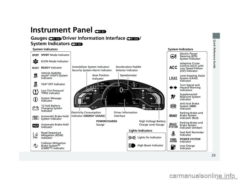
Instrument Panel (P 81)
Lights On Indicator
System Indicators
12-Volt Battery
Charging System
IndicatorAnti-lock Brake
System (
ABS)
Indicator
Vehicle Stability
Assist
® (VSA ®) System
Indicator
VSA ® OFF Indicator Electric Power
Steering (EPS)
System Indicator
Lights Indicators
High Beam Indicator
Seat Belt Reminder
Indicator
System Indicators
System Message
Indicator
Parking Brake and
Brake System
Indicator (Red) Supplemental
Restraint System
Indicator
Gauges (P 116)/Driver Information Interface (P 120)/
System Indicators
(P 82)
Low Tire Pressure/
TPMS Indicator Turn Signal and
Hazard Warning
Indicators
Speedometer
Automatic Brake Hold
System Indicator Parking Brake and
Brake System
Indicator (Amber)
SPORT Mode Indicator
Collision Mitigation
Brake System
TM
(CMBSTM) Indicator
Road Departure
Mitigation (RDM)
Indicator
Immobilizer System Indicator/
Security System Alarm Indicator
Automatic Brake Hold
IndicatorREADY Indicator
POWER SYSTEM
Indicator
Gear Position
Indicator
High Voltage Battery
Charge Level Gauge
Driver Information
Interface
Electricity Consumption
Indicator (
ENERGY USAGE )
POWER /CHARGE
Gauge
Low Charge
Indicator Adaptive Cruise
Control (ACC) with
Low Speed Follow
(LSF) Indicator
Lane Keeping Assist
System (LKAS)
Indicator
Deceleration Paddle
Selector Indicator
ECON Mode Indicator
18 CLARITY ELECTRIC CSS-31TRV6100.book 23 ページ 2018年2月5日 月曜日 午後12時0分
Page 33 of 559
31
Quick Reference Guide
Driving (P 359)
Electronic Gear Selector (P 371)
● Select
(P and depress the brake pedal when turning on the power.
Park
Press the
(P button.
Used when parking or before turning the power on or off.
Transmission is locked.
Reverse
Press back the
( R button.
Used when reversing.
Neutral
Press the
( N button.
Transmission is not locked.
Drive
Press the
( D button.
Used for normal driving.
The deceleration paddle selector can be used temporarily.
The deceleration paddle selector can be used when SPORT mode is on.
Gear Position Indicator
The gear position indicator
and the shift button
indicator indicate the
current gear selection.
Gear Position Indicator Shift Button
Indicator
Gear selection
18 CLARITY ELECTRIC CSS-31TRV6100.book 31 ページ 2018年2月5日 月曜日 午後12時0分
Page 35 of 559

33
Quick Reference Guide
Honda Sensing®
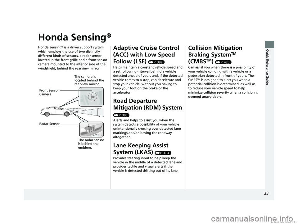
Honda Sensing® is a driver support system
which employs the use of two distinctly
different kinds of sensors, a radar sensor
located in the front grille and a front sensor
camera mounted to the interior side of the
windshield, behind the rearview mirror.
The camera is
located behind the
rearview mirror.
Front Sensor
Camera
Radar Sensor
The radar sensor
is behind the
emblem.
Adaptive Cruise Control
(ACC) with Low Speed
Follow (LSF)
(P 389)
Helps maintain a constant vehicle speed and
a set following-interval behind a vehicle
detected ahead of yours and, if the detected
vehicle comes to a stop, can decelerate and
stop your vehicle, without you having to
keep your foot on the brake or the
accelerator.
Road Departure
Mitigation (RDM) System
(P 385)
Alerts and helps to assist you when the
system detects a possibility of your vehicle
unintentionally crossing over detected lane
markings and/or leaving the roadway
altogether.
Lane Keeping Assist
System (LKAS)
(P 404)
Provides steering input to help keep the
vehicle in the middle of a detected lane and
provides tactile and visual alerts if the
vehicle is detected drifting out of its lane.
Collision Mitigation
Braking System
TM
(CMBS
TM) (P 428)
Can assist you when there is a possibility of
your vehicle colliding with a vehicle or a
pedestrian detected in front of yours. The
CMBS
TM is designed to alert you when a
potential collision is determined, as well as
to reduce your vehi cle speed to help
minimize collision severity when a collision is
deemed unavoidable.
18 CLARITY ELECTRIC CSS-31TRV6100.book 33 ページ 2018年2月5日 月曜日 午後12時0分
Page 36 of 559
34
Quick Reference Guide
Maintenance (P 457)
Under the Hood (P 465)
● Check coolants and windshield washer fluid. Add when
necessary.
● Check brake fluid.
● Check the 12-volt battery condition monthly.
aPull the hood release handle under the corner of the
dashboard.
bLocate the hood latch lever, push it to the side, and then
raise the hood. Once you have raised the hood slightly, you
can release the lever.
cWhen finished, close the hood and make sure it is firmly
locked in place.
Lights (P 470)
● Inspect all lights regularly.
Wiper Blades (P 472)
● Replace blades if they leave streaks
across the windshield.
Tires (P 475)
● Inspect tires and wheels regularly.
● Check tire pressures regularly.
● Install snow tires for winter driving.
18 CLARITY ELECTRIC CSS-31TRV6100.book 34 ページ 2018年2月5日 月曜日 午後12時0分