2018 HONDA CLARITY ELECTRIC audio
[x] Cancel search: audioPage 417 of 559
415
uuWhen Driving uTire Pressure Monitoring System (TPMS)
Driving
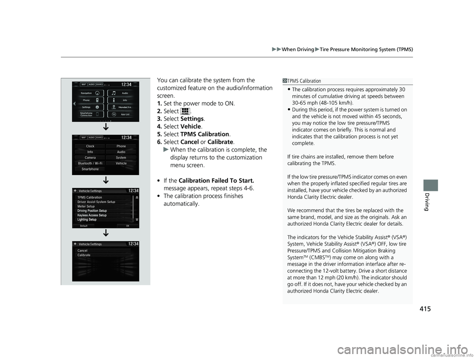
You can calibrate the system from the
customized feature on the audio/information
screen.
1. Set the power mode to ON.
2. Select .
3. Select Settings .
4. Select Vehicle .
5. Select TPMS Calibration .
6. Select Cancel or Calibrate .
u When the calibration is complete, the
display returns to the customization
menu screen.
• If the Calibration Failed To Start.
message appears, repeat steps 4-6.
• The calibration process finishes
automatically.1TPMS Calibration
•The calibration process requires approximately 30
minutes of cumulative dr iving at speeds between
30-65 mph (48-105 km/h).
•During this period, if the power system is turned on
and the vehicle is not moved within 45 seconds,
you may notice the low tire pressure/TPMS
indicator comes on briefl y. This is normal and
indicates that the calibr ation process is not yet
complete.
If tire chains are installed, remove them before
calibrating the TPMS.
If the low tire pressure/TPMS indicator comes on even
when the properly inflated specified regular tires are
installed, have your vehicl e checked by an authorized
Honda Clarity Electric dealer.
We recommend that the tires be replaced with the
same brand, model, and size as the originals. Ask an
authorized Honda Clarity El ectric dealer for details.
The indicators for the Vehicle Stability Assist ® (VSA ®)
System, Vehicle Stability Assist ® (VSA ®) OFF, low tire
Pressure/TPMS and Collision Mitigation Braking
System
TM (CMBSTM) may come on along with a
message in the driver information interface after re-
connecting the 12-volt battery. Drive a short distance
at more than 12 mph (20 km/h). The indicator should
go off. If it does not, have your vehicle checked by an
authorized Honda Clarity Electric dealer.
18 CLARITY ELECTRIC CSS-31TRV6100.book 415 ページ 2018年2月5日 月曜日 午後12時0分
Page 420 of 559
418
uuWhen Driving uLaneWatchTM
Driving
LaneWatchTM
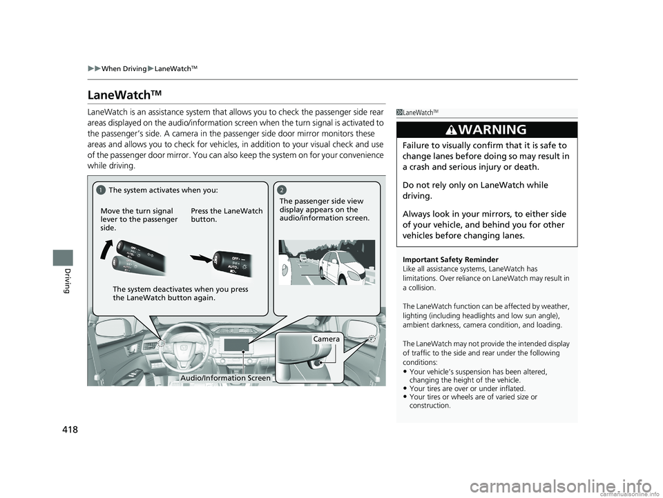
LaneWatch is an assistance system that allows you to check the passenger side rear
areas displayed on the audio/information screen when the turn signal is activated to
the passenger’s side. A camera in the pass enger side door mirror monitors these
areas and allows you to chec k for vehicles, in addition to your visual check and use
of the passenger door mirror. You can also keep the system on for your convenience
while driving.1 LaneWatchTM
Important Safety Reminder
Like all assistance systems, LaneWatch has
limitations. Over reliance on LaneWatch may result in
a collision.
The LaneWatch function can be affected by weather,
lighting (including headli ghts and low sun angle),
ambient darkness, camera condition, and loading.
The LaneWatch may not prov ide the intended display
of traffic to the side and rear under the following
conditions:
•Your vehicle’s suspensi on has been altered,
changing the height of the vehicle.
•Your tires are over or under inflated.•Your tires or wheels are of varied size or
construction.
3WARNING
Failure to visually confirm that it is safe to
change lanes before doing so may result in
a crash and serious injury or death.
Do not rely only on LaneWatch while
driving.
Always look in your mi rrors, to either side
of your vehicle, and behind you for other
vehicles before changing lanes.
12
Camera
Move the turn signal
lever to the passenger
side.
Press the LaneWatch
button.The passenger side view
display appears on the
audio/information screen.
The system activates when you:
The system deactivates when you press
the LaneWatch button again.
Audio/Information Screen
18 CLARITY ELECTRIC CSS-31TRV6100.book 418 ページ 2018年2月5日 月曜日 午後12時0分
Page 421 of 559
419
uuWhen Driving uLaneWatchTM
Driving
■Customizing the La neWatch settings
You can customize the following items using the audio/information screen.
• Show with Turn Signal : Selects whether LaneWatch monitor comes on when
you operate the turn signal light lever.
• Display Time after Turn Signal Off : Changes the length of time the LaneWatch
display stays on after you pull the turn signal lever back.
• Reference Line : Selects whether the reference lines appear on the LaneWatch
monitor.
• Display : Allows for display adjustments of items, such as brightness, contrast and
black level. This setting is part of the System setup group.
2Customized Features P. 296
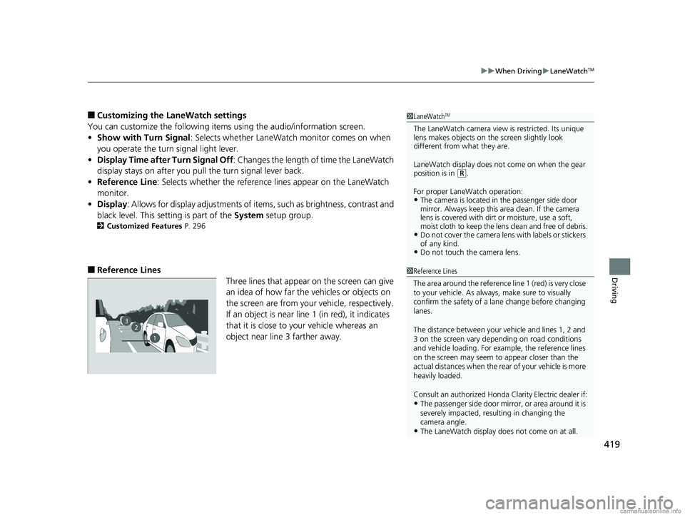
■Reference Lines
Three lines that appear on the screen can give
an idea of how far the vehicles or objects on
the screen are from your vehicle, respectively.
If an object is near line 1 (in red), it indicates
that it is close to your vehicle whereas an
object near line 3 farther away.
1LaneWatchTM
The LaneWatch camera view is restricted. Its unique
lens makes objects on the screen slightly look
different from what they are.
LaneWatch display does not come on when the gear
position is in
( R.
For proper LaneWatch operation:
•The camera is located in the passenger side door
mirror. Always keep this area clean. If the camera
lens is covered with dirt or moisture, use a soft,
moist cloth to keep the lens clean and free of debris.
•Do not cover the camera lens with labels or stickers
of any kind.
•Do not touch the camera lens.
23
1
1Reference Lines
The area around the reference li ne 1 (red) is very close
to your vehicle. As always, make sure to visually
confirm the safety of a la ne change before changing
lanes.
The distance betwee n your vehicle and lines 1, 2 and
3 on the screen vary depending on road conditions
and vehicle loading. For ex ample, the reference lines
on the screen may seem to appear closer than the
actual distances when the rear of your vehicle is more
heavily loaded.
Consult an authorized Honda Clarity Electric dealer if:
•The passenger side door mirr or, or area around it is
severely impacted, resulting in changing the
camera angle.
•The LaneWatch display doe s not come on at all.
18 CLARITY ELECTRIC CSS-31TRV6100.book 419 ページ 2018年2月5日 月曜日 午後12時0分
Page 431 of 559
Continued429
uuBraking uCollision Mitigation Braking SystemTM (CMBSTM)
Driving
■When the system activates
At system’s earliest collision alert st age, you can change the distance (Long/
Normal /Short ) between vehicles at which alerts will come on through audio/
information screen setting options.
2 Customized Features P. 296
■Vibration alert on the steering wheel
When a potential collision to an oncoming detected vehicle is determined, the
system alerts you with rapid vibration on the steering wheel, in addition to visual and
audible alerts. u Take appropriate action to prevent a col lision (apply the brakes, operate the
steering wheel, etc.).
1 When the system activates
The camera in the CMBS
TM is also designed to detect
pedestrians.
However, this pedestrian detection feature may not
activate or may not detect a pedestrian in front of
your vehicle under certain conditions.
Refer to the ones indicating the pedestrian detection
limitations from the list. 2 CMBS
TM Conditions and Limitations P. 432
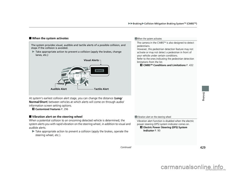
The system provides visual, audible and tactile alerts of a possible collision, and
stops if the collision is avoided.
u Take appropriate action to prevent a collision (apply the brakes, change
lanes, etc.)
Beep Visual Alerts
Audible Alert
Tactile Alert
1 Vibration alert on the steering wheel
Vibration alert function is disabled when the electric
power steering (EPS) system indicator comes on.
2 Electric Power Steering (EPS) System
Indicator P. 90
18 CLARITY ELECTRIC CSS-31TRV6100.book 429 ページ 2018年2月5日 月曜日 午後12時0分
Page 440 of 559
438
Driving
Multi-View Rear Camera
About Your Multi-View Rear Camera
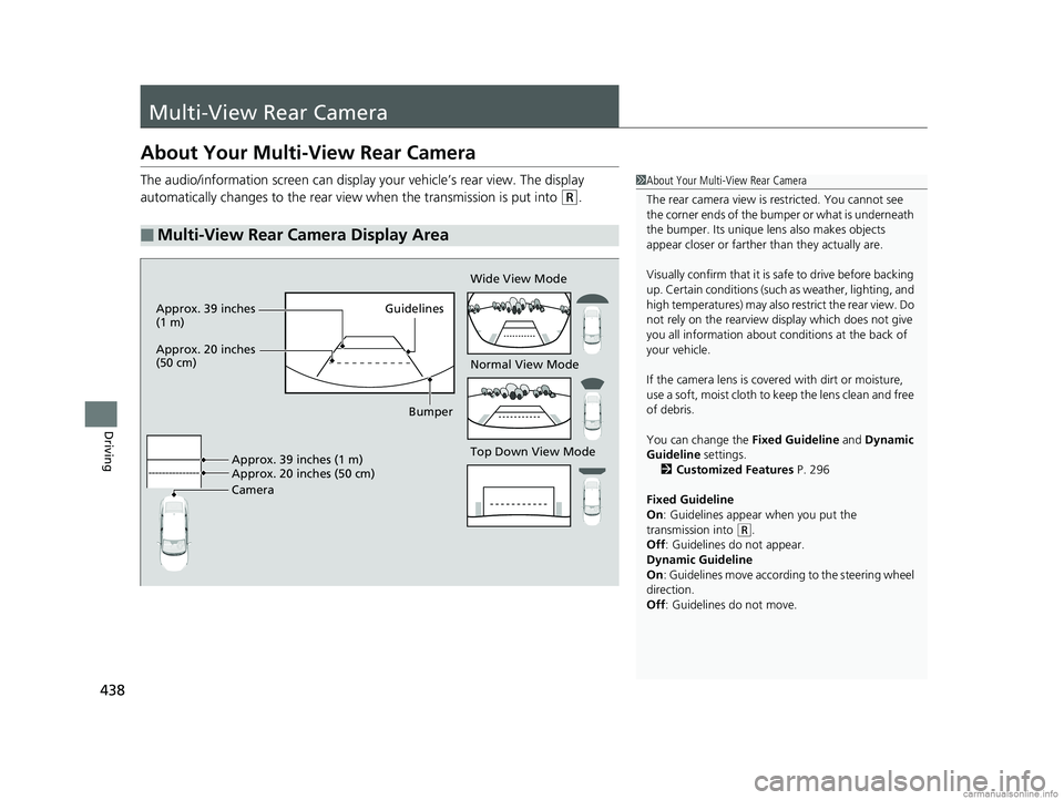
The audio/information screen can display your vehicle’s rear view. The display
automatically changes to the rear view when the transmission is put into
(R.
■Multi-View Rear Camera Display Area
1About Your Multi-View Rear Camera
The rear camera view is restricted. You cannot see
the corner ends of the bum per or what is underneath
the bumper. Its unique le ns also makes objects
appear closer or farther than they actually are.
Visually confirm that it is safe to drive before backing
up. Certain conditions (such as weather, lighting, and
high temperatures) may also restrict the rear view. Do
not rely on the rearview display which does not give
you all information about conditions at the back of
your vehicle.
If the camera lens is cove red with dirt or moisture,
use a soft, moist cloth to keep the lens clean and free
of debris.
You can change the Fixed Guideline and Dynamic
Guideline settings.
2 Customized Features P. 296
Fixed Guideline
On : Guidelines appear when you put the
transmission into
( R.
Off : Guidelines do not appear.
Dynamic Guideline
On : Guidelines move according to the steering wheel
direction.
Off : Guidelines do not move.
Top Down View Mode Normal View Mode Wide View Mode
Guidelines
Bumper
Camera Approx. 39 inches (1 m)
Approx. 20 inches (50 cm)
Approx. 39 inches
(1 m)
Approx. 20 inches
(50 cm)
18 CLARITY ELECTRIC CSS-31TRV6100.book 438 ページ 2018年2月5日 月曜日 午後12時0分
Page 466 of 559
uuMaintenance MinderTMuTo Use Maintenance MinderTM
464
Maintenance
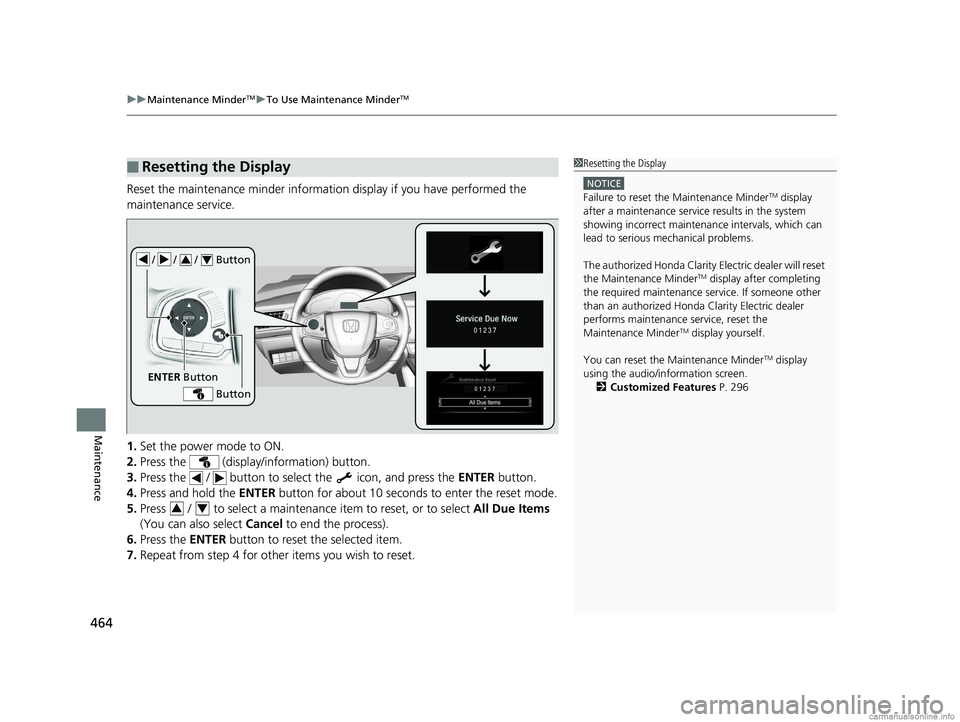
Reset the maintenance minder informat ion display if you have performed the
maintenance service.
1. Set the power mode to ON.
2. Press the (display/information) button.
3. Press the / button to sele ct the icon, and press the ENTER button.
4. Press and hold the ENTER button for about 10 seconds to enter the reset mode.
5. Press / to select a maintenance item to reset, or to select All Due Items
(You can also select Cancel to end the process).
6. Press the ENTER button to reset the selected item.
7. Repeat from step 4 for other items you wish to reset.
■Resetting the Display1Resetting the Display
NOTICE
Failure to reset the Maintenance MinderTM display
after a maintenance servic e results in the system
showing incorrect maintenance intervals, which can
lead to serious mechanical problems.
The authorized Honda Clarity Electric dealer will reset
the Maintenance Minder
TM display after completing
the required maintenance service. If someone other
than an authorized Honda Clarity Electric dealer
performs maintenance service, reset the
Maintenance Minder
TM display yourself.
You can reset the Maintenance Minder
TM display
using the audio/information screen. 2 Customized Features P. 296
/ / / Button34
ENTER Button
Button
34
18 CLARITY ELECTRIC CSS-31TRV6100.book 464 ページ 2018年2月5日 月曜日 午後12時0分
Page 486 of 559
484
Maintenance
12-Volt Battery
Checking the 12-Volt Battery
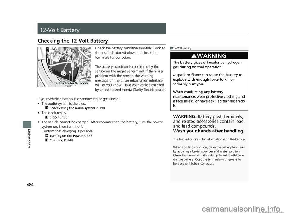
Check the battery condition monthly. Look at
the test indicator window and check the
terminals for corrosion.
The battery condition is monitored by the
sensor on the negative terminal. If there is a
problem with the sensor, the warning
message on the driver information interface
will let you know. Have your vehicle checked
by an authorized Honda Clarity Electric dealer.
If your vehicle’s battery is disconnected or goes dead:
• The audio system is disabled.
2 Reactivating the audio system P. 198
•The clock resets.
2 Clock P. 130
•The vehicle cannot be charged. After reconnecting the batte ry, turn the power
system on, then turn it off.
Confirm that charging is possible.
2 Turning on the Power P. 366
2 Charging P. 440
112-Volt Battery
WARNING: Battery post, terminals,
and related accessories contain lead
and lead compounds.
Wash your hands after handling.
The test indicator’s color in formation is on the battery.
When you find corrosion, cl ean the battery terminals
by applying a baking powder and water solution.
Clean the terminals with a damp towel. Cloth/towel
dry the battery. Coat the terminals with grease to
help prevent future corrosion.
3WARNING
The battery gives off explosive hydrogen
gas during normal operation.
A spark or flame can cause the battery to
explode with enough force to kill or
seriously hurt you.
When conducting any battery
maintenance, wear prot ective clothing and
a face shield, or have a skilled technician do
it.
Test Indicator Window
18 CLARITY ELECTRIC CSS-31TRV6100.book 484 ページ 2018年2月5日 月曜日 午後12時0分
Page 490 of 559
488
Maintenance
Cleaning
Interior Care
Use a damp cloth with a mixture of mild detergent and warm water to remove dirt.
Use a clean cloth to remove detergent residue.
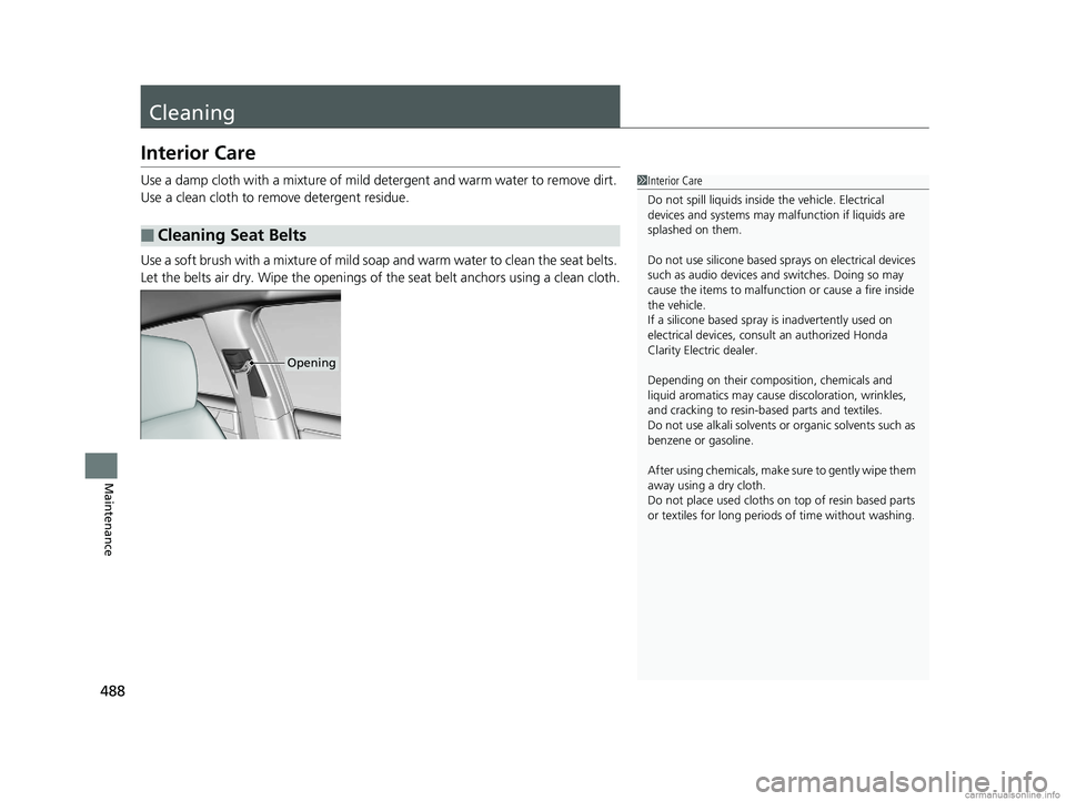
Use a soft brush with a mixture of mild soap and warm water to clean the seat belts.
Let the belts air dry. Wipe the openings of the seat belt anchors using a clean cloth.
■Cleaning Seat Belts
1 Interior Care
Do not spill liquids inside the vehicle. Electrical
devices and systems may ma lfunction if liquids are
splashed on them.
Do not use silicone based sprays on electrical devices
such as audio devices and switches. Doing so may
cause the items to malfunction or cause a fire inside
the vehicle.
If a silicone based spray is inadvertently used on
electrical devices, cons ult an authorized Honda
Clarity Electric dealer.
Depending on their compos ition, chemicals and
liquid aromatics may cause discoloration, wrinkles,
and cracking to resin-ba sed parts and textiles.
Do not use alkali solvents or organic solvents such as
benzene or gasoline.
After using chemical s, make sure to gently wipe them
away using a dry cloth.
Do not place used cloths on top of resin based parts
or textiles for long periods of time without washing.
Opening
18 CLARITY ELECTRIC CSS-31TRV6100.book 488 ページ 2018年2月5日 月曜日 午後12時0分