2018 FORD F250 SUPER DUTY ECU
[x] Cancel search: ECUPage 371 of 656
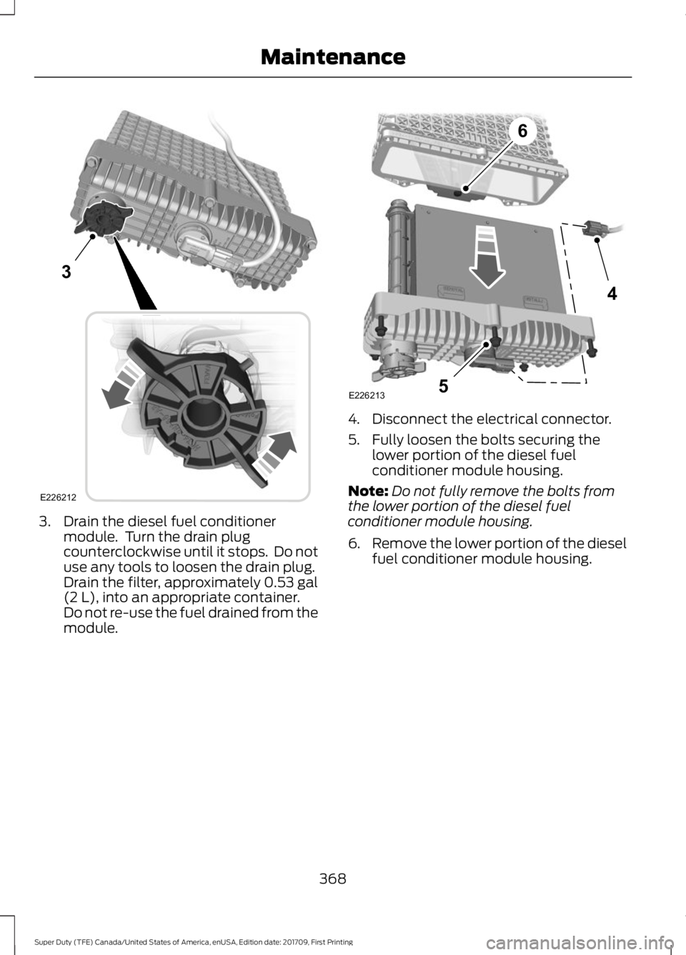
3. Drain the diesel fuel conditioner
module. Turn the drain plug
counterclockwise until it stops. Do not
use any tools to loosen the drain plug.
Drain the filter, approximately 0.53 gal
(2 L), into an appropriate container.
Do not re-use the fuel drained from the
module. 4. Disconnect the electrical connector.
5. Fully loosen the bolts securing the
lower portion of the diesel fuel
conditioner module housing.
Note: Do not fully remove the bolts from
the lower portion of the diesel fuel
conditioner module housing.
6. Remove the lower portion of the diesel
fuel conditioner module housing.
368
Super Duty (TFE) Canada/United States of America, enUSA, Edition date: 201709, First Printing Maintenance3
E226212 4
5
6
E226213
Page 372 of 656
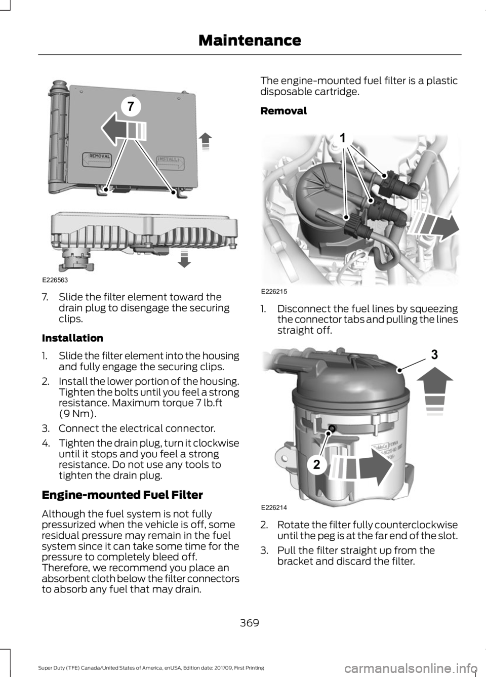
7. Slide the filter element toward the
drain plug to disengage the securing
clips.
Installation
1. Slide the filter element into the housing
and fully engage the securing clips.
2. Install the lower portion of the housing.
Tighten the bolts until you feel a strong
resistance. Maximum torque 7 lb.ft
(9 Nm).
3. Connect the electrical connector.
4. Tighten the drain plug, turn it clockwise
until it stops and you feel a strong
resistance. Do not use any tools to
tighten the drain plug.
Engine-mounted Fuel Filter
Although the fuel system is not fully
pressurized when the vehicle is off, some
residual pressure may remain in the fuel
system since it can take some time for the
pressure to completely bleed off.
Therefore, we recommend you place an
absorbent cloth below the filter connectors
to absorb any fuel that may drain. The engine-mounted fuel filter is a plastic
disposable cartridge.
Removal
1.
Disconnect the fuel lines by squeezing
the connector tabs and pulling the lines
straight off. 2.
Rotate the filter fully counterclockwise
until the peg is at the far end of the slot.
3. Pull the filter straight up from the bracket and discard the filter.
369
Super Duty (TFE) Canada/United States of America, enUSA, Edition date: 201709, First Printing Maintenance7
E226563 E226215
1 E226214
2
3
Page 403 of 656
USING SNOW CHAINS
WARNING
Snow tires must be the same size,
load index, speed rating as those
originally provided by Ford. Use of
any tire or wheel not recommended by
Ford can affect the safety and
performance of your vehicle, which could
result in an increased risk of loss of vehicle
control, vehicle rollover, personal injury and
death. Additionally, the use of
non-recommended tires and wheels could
cause steering, suspension, axle, transfer
case or power transfer unit failure. Note:
Do not use snow chains on vehicles
with 20 inch wheels and tires.
The tires on your vehicle have all-weather
treads to provide traction in rain and snow.
However, in some climates, you may need
to use snow tires and cables. If you need
to use cables, it is recommended that steel
wheels (of the same size and
specifications) be used, as cables may chip
aluminum wheels.
Note: The suspension insulation and
bumpers will help prevent vehicle damage.
Do not remove these components from your
vehicle when using snow tires and chains.
Follow these guidelines when using snow
tires and chains:
• If possible, avoid fully loading your
vehicle
• Use only SAE Class S chains.
• Install chains securely, verifying that
the chains do not touch any wiring,
brake lines or fuel lines. •
Drive cautiously. If you hear the chains
rub or bang against your vehicle, stop
and retighten the chains. If this does
not work, remove the chains to prevent
damage to your vehicle.
• Remove the tire chains when they are
no longer needed. Do not use tire
chains on dry roads.
If you have any questions regarding snow
chains or cables, please contact your
authorized dealer.
TIRE PRESSURE MONITORING
SYSTEM
Vehicle Tire Pressure Monitoring
System WARNING
The tire pressure monitoring system
is not a substitute for manually
checking tire pressures. You should
periodically check tire pressures using a
pressure gauge. Failure to correctly
maintain tire pressures could increase the
risk of tire failure, loss of control, vehicle
rollover and personal injury. Each tire, including the spare (if
provided), should be checked
monthly when cold and inflated
to the inflation pressure recommended by
the vehicle manufacturer on the vehicle
placard or tire inflation pressure label. (If
your vehicle has tires of a different size
than the size indicated on the vehicle
placard or tire inflation pressure label, you
should determine the proper tire inflation
pressure for those tires.)
400
Super Duty (TFE) Canada/United States of America, enUSA, Edition date: 201709, First Printing Wheels and Tires
Page 414 of 656
Tire Change Procedure
WARNINGS
When one of the front wheels is off
the ground, the transmission alone
will not prevent the vehicle from
moving or slipping off the jack, even if the
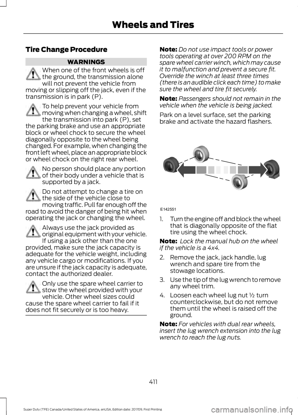
transmission is in park (P). To help prevent your vehicle from
moving when changing a wheel, shift
the transmission into park (P), set
the parking brake and use an appropriate
block or wheel chock to secure the wheel
diagonally opposite to the wheel being
changed. For example, when changing the
front left wheel, place an appropriate block
or wheel chock on the right rear wheel. No person should place any portion
of their body under a vehicle that is
supported by a jack.
Do not attempt to change a tire on
the side of the vehicle close to
moving traffic. Pull far enough off the
road to avoid the danger of being hit when
operating the jack or changing the wheel. Always use the jack provided as
original equipment with your vehicle.
If using a jack other than the one
provided, make sure the jack capacity is
adequate for the vehicle weight, including
any vehicle cargo or modifications. If you
are unsure if the jack capacity is adequate,
contact the authorized dealer. Only use the spare wheel carrier to
stow the wheel provided with your
vehicle. Other wheel sizes could
cause the spare wheel carrier to fail if it
does not fit securely or is too heavy. Note:
Do not use impact tools or power
tools operating at over 200 RPM on the
spare wheel carrier winch, which may cause
it to malfunction and prevent a secure fit.
Override the winch at least three times
(there is an audible click each time) to make
sure the wheel and tire fit securely.
Note: Passengers should not remain in the
vehicle when the vehicle is being jacked.
Park on a level surface, set the parking
brake and activate the hazard flashers. 1.
Turn the engine off and block the wheel
that is diagonally opposite of the flat
tire using the wheel chock.
Note: Lock the manual hub on the wheel
if the vehicle is a 4x4.
2. Remove the jack, jack handle, lug wrench and spare tire from the
stowage locations.
3. Use the tip of the lug wrench to remove
any wheel trim.
4. Loosen each wheel lug nut ½ turn counterclockwise, but do not remove
them until the wheel is raised off the
ground.
Note: For vehicles with dual rear wheels,
insert the lug wrench extension into the lug
wrench to reach the lug nuts.
411
Super Duty (TFE) Canada/United States of America, enUSA, Edition date: 201709, First Printing Wheels and TiresE142551
Page 416 of 656

Rear
Note:
Jack at the specified locations to
avoid damage to the vehicle.
Jacking the Vehicle 1. Turn the jack handle clockwise until
the wheel is completely off the ground
and high enough to install the spare
tire.
2. Remove the lug nuts with the lug wrench.
3. Replace the flat tire with the spare tire,
making sure the valve stem is facing
outward for all front wheels and single
rear wheel vehicles. If you are replacing
an inboard rear tire on dual rear wheel
vehicles, the valve stem must be facing
outward. If you are replacing the
outboard wheel, the valve stem must
be facing inward. Reinstall the lug nuts
until the wheel is snug against the hub.
Do not fully tighten the lug nuts until
the wheel has been lowered.
4. Lower the wheel by turning the jack handle counterclockwise.
5. Remove the jack and fully tighten the lug nuts in the order shown. See
Technical Specifications (page 419).
6. Stow the flat tire. See Stowing the flat or spare tire if the vehicle is equipped
with a spare tire carrier. 7. Stow the jack, jack handle and lug
wrench. Make sure the jack is securely
fastened so it does not rattle when
driving.
8. Unblock the wheels. 8-lug nut torque sequence
10-lug nut torque sequence
413
Super Duty (TFE) Canada/United States of America, enUSA, Edition date: 201709, First Printing Wheels and TiresE162811 E161441
13
4
27
6
5
8 1
2
3
4
5
6
7 8
9
10
E169375 E162820
Page 419 of 656

2. Use an up-and-down motion with the
jack handle to raise the wheel
completely off the ground.
Note: Hydraulic jacks are equipped with a
pressure release valve that prevents lifting
loads which exceed the jack's rated
capacity.
3. Remove the lug nuts with the lug wrench.
4. Replace the flat tire with the spare tire,
making sure the valve stem is facing
outward on all front an inboard rear
wheels. If you are replacing the
outboard wheel, the valve stem must
be facing inward. Reinstall the lug nuts
until the wheel is snug against the hub.
Do not fully tighten the lug nuts until
the wheel has been lowered.
5. Lower the wheel by slowly turning the release valve counterclockwise.
Opening the release valve slowly will
provide a more controlled rate of
descent.
6. Remove the jack and fully tighten the lug nuts in the order shown. See
Technical Specifications (page 419).
7. Stow the flat tire. See Stowing the flat or spare tire if the vehicle is equipped
with a spare tire carrier.
8. Stow the jack, jack handle and lug wrench. Make sure the jack is securely
fastened so it does not rattle when
driving.
9. Unblock the wheels. 8-lug nut torque sequence
10-lug nut torque sequence
Installing Dual Rear Wheel Ornaments
1. Align the ornament with the lug nuts.
A is the clip and B is the flange.
416
Super Duty (TFE) Canada/United States of America, enUSA, Edition date: 201709, First Printing Wheels and TiresE161441
13
4
27
6
5
8 1
2
3
4
5
6
7 8
9
10
E169375 AB
E162822
Page 422 of 656

TECHNICAL SPECIFICATIONS
Wheel Lug Nut Torque Specifications
WARNING
When a wheel is installed, always remove any corrosion, dirt or foreign materials
present on the mounting surfaces of the wheel or the surface of the wheel hub,
brake drum or brake disc that contacts the wheel. Make sure that any fasteners
that attach the rotor to the hub are secured so they do not interfere with the mounting
surfaces of the wheel. Installing wheels without correct metal-to-metal contact at the
wheel mounting surfaces can cause the wheel nuts to loosen and the wheel to come off
while the vehicle is in motion, resulting in loss of control. lb.ft (Nm)
Bolt size
165 lb.ft (224 Nm)
M14 x 1.5
* Torque specifications are for nut and bolt threads free of dirt and rust. Use only Ford
recommended replacement fasteners.
On vehicles equipped with single rear wheels, retighten the lug nuts to the specified torque
at 100 miles (160 kilometers) after any wheel disturbance (such as tire rotation, changing
a flat tire, wheel removal).
On vehicles equipped with dual rear wheels, retighten the wheel lug nuts to the specified
torque at 100 miles (160 kilometers), and again at 500 miles (800 kilometers) of new
vehicle operation and after any wheel disturbance (such as tire rotation, changing a flat
tire, wheel removal).
It is important to follow the proper wheel mounting and lug nut torque procedures.
On all two-piece flat wheel nuts, apply one drop of motor oil between the flat washer
and the nut. Do not apply motor oil to the wheel nut threads or the wheel stud threads. 419
Super Duty (TFE) Canada/United States of America, enUSA, Edition date: 201709, First Printing Wheels and TiresE161443
Page 477 of 656
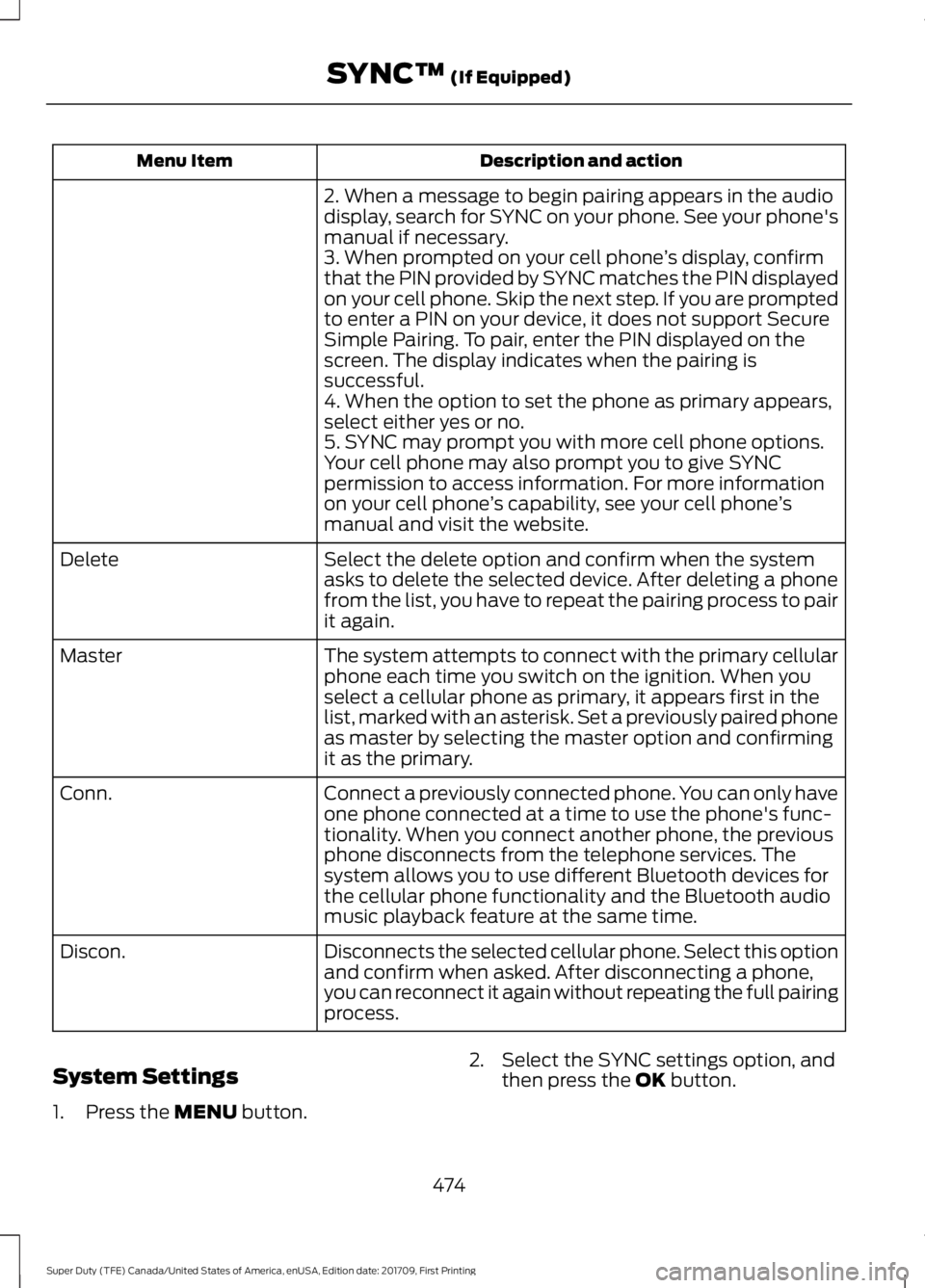
Description and action
Menu Item
2. When a message to begin pairing appears in the audio
display, search for SYNC on your phone. See your phone's
manual if necessary.
3. When prompted on your cell phone ’s display, confirm
that the PIN provided by SYNC matches the PIN displayed
on your cell phone. Skip the next step. If you are prompted
to enter a PIN on your device, it does not support Secure
Simple Pairing. To pair, enter the PIN displayed on the
screen. The display indicates when the pairing is
successful.
4. When the option to set the phone as primary appears,
select either yes or no.
5. SYNC may prompt you with more cell phone options.
Your cell phone may also prompt you to give SYNC
permission to access information. For more information
on your cell phone ’s capability, see your cell phone ’s
manual and visit the website.
Select the delete option and confirm when the system
asks to delete the selected device. After deleting a phone
from the list, you have to repeat the pairing process to pair
it again.
Delete
The system attempts to connect with the primary cellular
phone each time you switch on the ignition. When you
select a cellular phone as primary, it appears first in the
list, marked with an asterisk. Set a previously paired phone
as master by selecting the master option and confirming
it as the primary.
Master
Connect a previously connected phone. You can only have
one phone connected at a time to use the phone's func-
tionality. When you connect another phone, the previous
phone disconnects from the telephone services. The
system allows you to use different Bluetooth devices for
the cellular phone functionality and the Bluetooth audio
music playback feature at the same time.
Conn.
Disconnects the selected cellular phone. Select this option
and confirm when asked. After disconnecting a phone,
you can reconnect it again without repeating the full pairing
process.
Discon.
System Settings
1. Press the MENU button. 2. Select the SYNC settings option, and
then press the
OK button.
474
Super Duty (TFE) Canada/United States of America, enUSA, Edition date: 201709, First Printing SYNC™
(If Equipped)