2018 FORD F250 SUPER DUTY ECU
[x] Cancel search: ECUPage 136 of 656
AdvanceTrac and Traction Control
Action
Message
The system detects a condition that requires service. Contactan authorized dealer as soon as possible.
Service AdvanceTrac
The status of the AdvanceTrac system after you switched it off.
AdvanceTrac Off
The status of the AdvanceTrac system after you switched it on.
AdvanceTrac On
The status of the AdvanceTrac sport mode after you switched it on.
AdvanceTrac SPORT
MODE
The status of the traction control system after you switchedit off. See Using Traction Control (page 231).
Traction Control Off
The status of the traction control system after you switchedit on. See
Using Traction Control (page 231).
Traction Control On
Airbag Action
Message
Displays when the system detects a malfunction due to a blocked sensor.
Occupant Sensor
BLOCKED Remove
Objects Near Passenger Seat
Alarm and Security Action
Message
Alarm triggered due to unauthorized entry. See
Anti-Theft
Alarm (page 78).
Vehicle Alarm To Stop
Alarm, Start Vehicle.
133
Super Duty (TFE) Canada/United States of America, enUSA, Edition date: 201709, First Printing Information Displays
Page 171 of 656
HomeLink Wireless Control
System
WARNINGS
Make sure that the garage door and
security device are free from
obstruction when you are
programming. Do not program the system
with the vehicle in the garage. Do not use the system with any
garage door opener that does not
have the safety stop and reverse
feature as required by U.S. Federal Safety
Standards (this includes any garage door
opener manufactured before April 1, 1982).
A garage door opener which cannot detect
an object, signaling the door to stop and
reverse, does not meet current federal
safety standards. Using a garage door
opener without these features increases
the risk of serious injury or death. Note:
Make sure you keep the original
remote control transmitter for use in other
vehicles as well as for future system
programming.
Note: We recommend that upon the sale
or lease termination of your vehicle, you
erase the programmed function buttons for
security reasons. See Erasing the Function
Button Codes later in this section.
Note: You can program a maximum of
three devices. To change or replace any of
the three devices after it has been initially
programmed, you must first erase the
current settings. See Erasing the Function
Button Codes
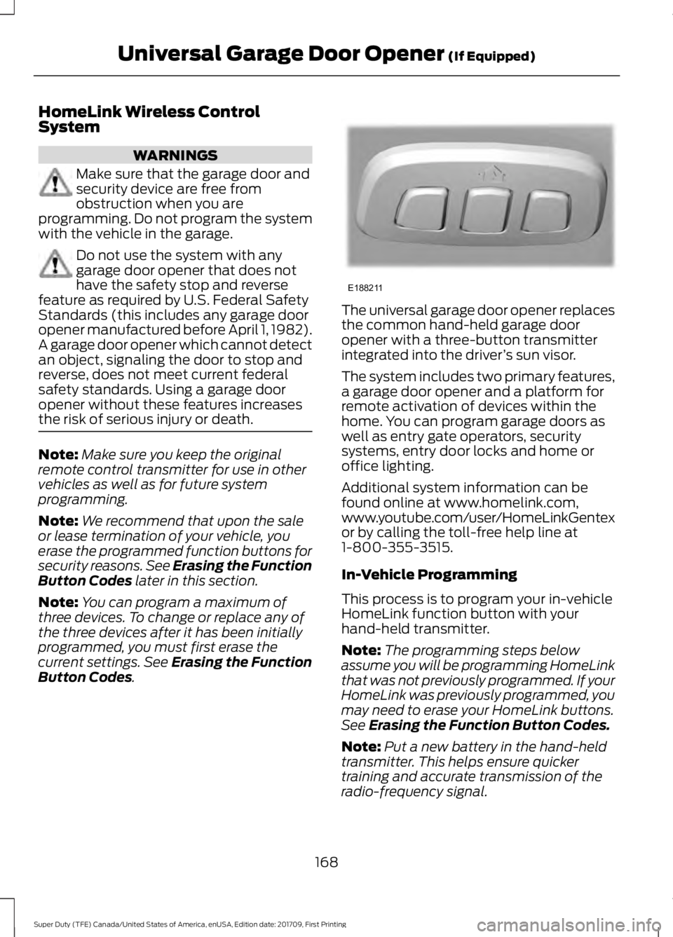
. The universal garage door opener replaces
the common hand-held garage door
opener with a three-button transmitter
integrated into the driver
’s sun visor.
The system includes two primary features,
a garage door opener and a platform for
remote activation of devices within the
home. You can program garage doors as
well as entry gate operators, security
systems, entry door locks and home or
office lighting.
Additional system information can be
found online at www.homelink.com,
www.youtube.com/user/HomeLinkGentex
or by calling the toll-free help line at
1-800-355-3515.
In-Vehicle Programming
This process is to program your in-vehicle
HomeLink function button with your
hand-held transmitter.
Note: The programming steps below
assume you will be programming HomeLink
that was not previously programmed. If your
HomeLink was previously programmed, you
may need to erase your HomeLink buttons.
See
Erasing the Function Button Codes.
Note: Put a new battery in the hand-held
transmitter. This helps ensure quicker
training and accurate transmission of the
radio-frequency signal.
168
Super Duty (TFE) Canada/United States of America, enUSA, Edition date: 201709, First Printing Universal Garage Door Opener
(If Equipped)E188211
Page 213 of 656
AUTOMATIC TRANSMISSION
WARNINGS
Always fully apply the parking brake.
Make sure you shift into park (P) for
vehicles with an automatic
transmission. Switch the ignition off and
remove the key whenever you leave your
vehicle. When your vehicle is stationary, keep
the brake pedal fully pressed when
shifting gears. Failure to follow this
instruction could result in personal injury,
death or property damage. Note:
You may not be able to shift out of
park (P) unless the intelligent access key is
inside your vehicle.
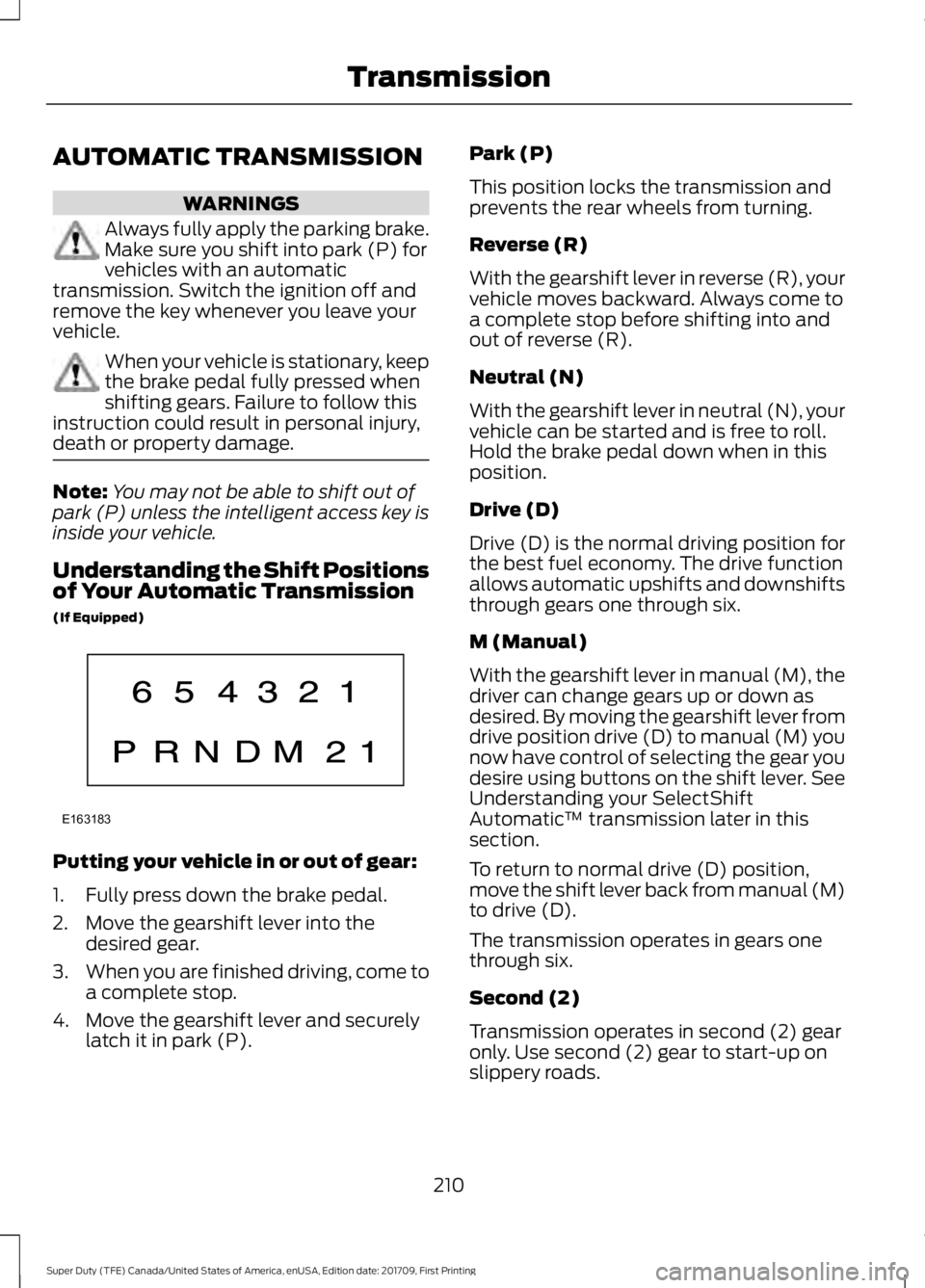
Understanding the Shift Positions
of Your Automatic Transmission
(If Equipped) Putting your vehicle in or out of gear:
1. Fully press down the brake pedal.
2. Move the gearshift lever into the
desired gear.
3. When you are finished driving, come to
a complete stop.
4. Move the gearshift lever and securely latch it in park (P). Park (P)
This position locks the transmission and
prevents the rear wheels from turning.
Reverse (R)
With the gearshift lever in reverse (R), your
vehicle moves backward. Always come to
a complete stop before shifting into and
out of reverse (R).
Neutral (N)
With the gearshift lever in neutral (N), your
vehicle can be started and is free to roll.
Hold the brake pedal down when in this
position.
Drive (D)
Drive (D) is the normal driving position for
the best fuel economy. The drive function
allows automatic upshifts and downshifts
through gears one through six.
M (Manual)
With the gearshift lever in manual (M), the
driver can change gears up or down as
desired. By moving the gearshift lever from
drive position drive (D) to manual (M) you
now have control of selecting the gear you
desire using buttons on the shift lever. See
Understanding your SelectShift
Automatic
™ transmission later in this
section.
To return to normal drive (D) position,
move the shift lever back from manual (M)
to drive (D).
The transmission operates in gears one
through six.
Second (2)
Transmission operates in second (2) gear
only. Use second (2) gear to start-up on
slippery roads.
210
Super Duty (TFE) Canada/United States of America, enUSA, Edition date: 201709, First Printing TransmissionE163183
Page 217 of 656
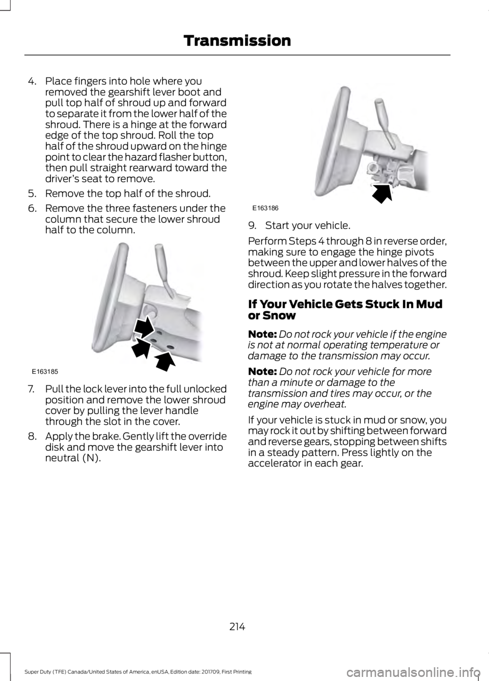
4. Place fingers into hole where you
removed the gearshift lever boot and
pull top half of shroud up and forward
to separate it from the lower half of the
shroud. There is a hinge at the forward
edge of the top shroud. Roll the top
half of the shroud upward on the hinge
point to clear the hazard flasher button,
then pull straight rearward toward the
driver ’s seat to remove.
5. Remove the top half of the shroud.
6. Remove the three fasteners under the column that secure the lower shroud
half to the column. 7.
Pull the lock lever into the full unlocked
position and remove the lower shroud
cover by pulling the lever handle
through the slot in the cover.
8. Apply the brake. Gently lift the override
disk and move the gearshift lever into
neutral (N). 9. Start your vehicle.
Perform Steps 4 through 8 in reverse order,
making sure to engage the hinge pivots
between the upper and lower halves of the
shroud. Keep slight pressure in the forward
direction as you rotate the halves together.
If Your Vehicle Gets Stuck In Mud
or Snow
Note:
Do not rock your vehicle if the engine
is not at normal operating temperature or
damage to the transmission may occur.
Note: Do not rock your vehicle for more
than a minute or damage to the
transmission and tires may occur, or the
engine may overheat.
If your vehicle is stuck in mud or snow, you
may rock it out by shifting between forward
and reverse gears, stopping between shifts
in a steady pattern. Press lightly on the
accelerator in each gear.
214
Super Duty (TFE) Canada/United States of America, enUSA, Edition date: 201709, First Printing TransmissionE163185 E163186
Page 275 of 656
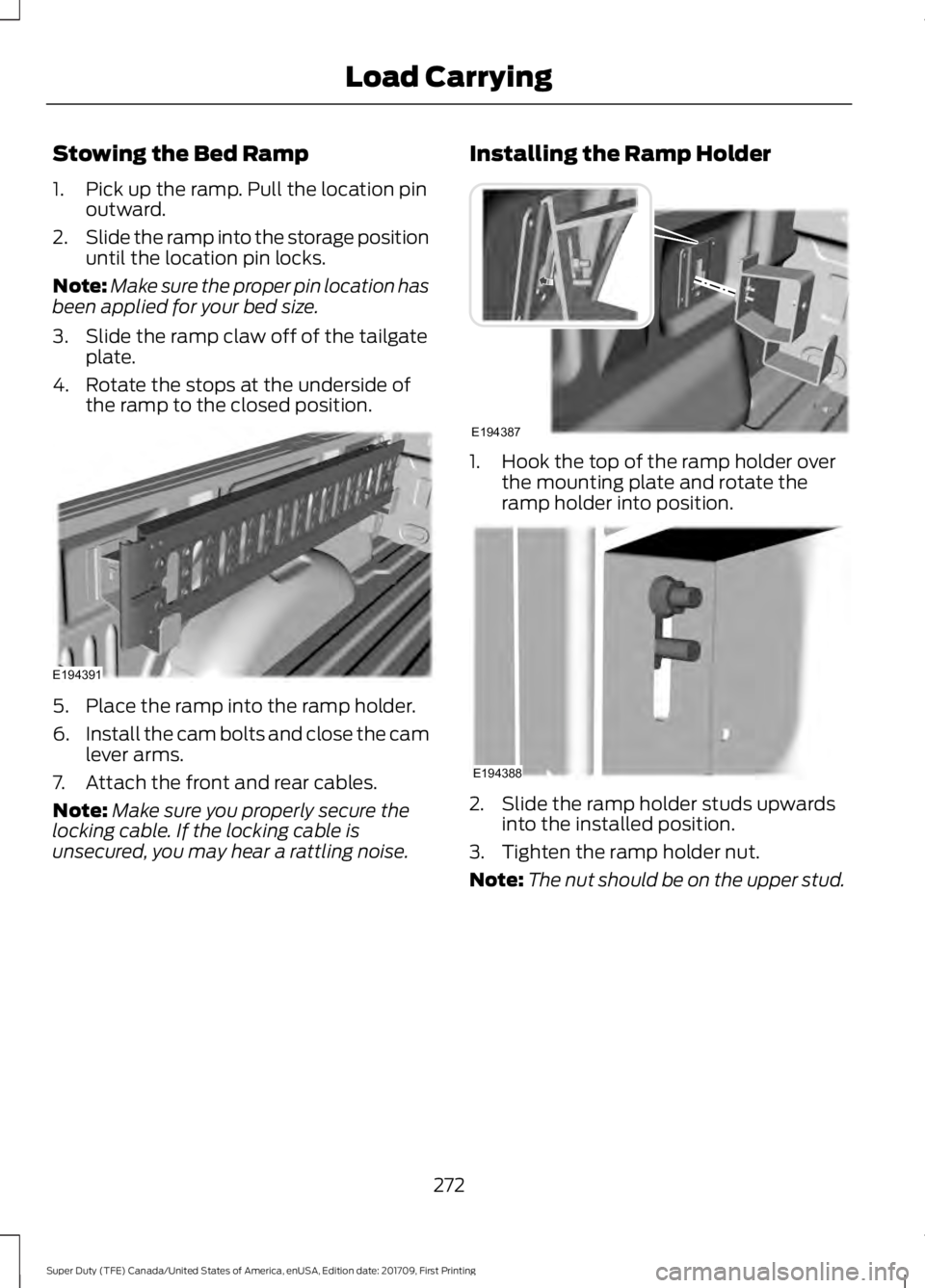
Stowing the Bed Ramp
1. Pick up the ramp. Pull the location pin
outward.
2. Slide the ramp into the storage position
until the location pin locks.
Note: Make sure the proper pin location has
been applied for your bed size.
3. Slide the ramp claw off of the tailgate plate.
4. Rotate the stops at the underside of the ramp to the closed position. 5. Place the ramp into the ramp holder.
6.
Install the cam bolts and close the cam
lever arms.
7. Attach the front and rear cables.
Note: Make sure you properly secure the
locking cable. If the locking cable is
unsecured, you may hear a rattling noise. Installing the Ramp Holder 1. Hook the top of the ramp holder over
the mounting plate and rotate the
ramp holder into position. 2. Slide the ramp holder studs upwards
into the installed position.
3. Tighten the ramp holder nut.
Note: The nut should be on the upper stud.
272
Super Duty (TFE) Canada/United States of America, enUSA, Edition date: 201709, First Printing Load CarryingE194391 E194387 E194388
Page 293 of 656
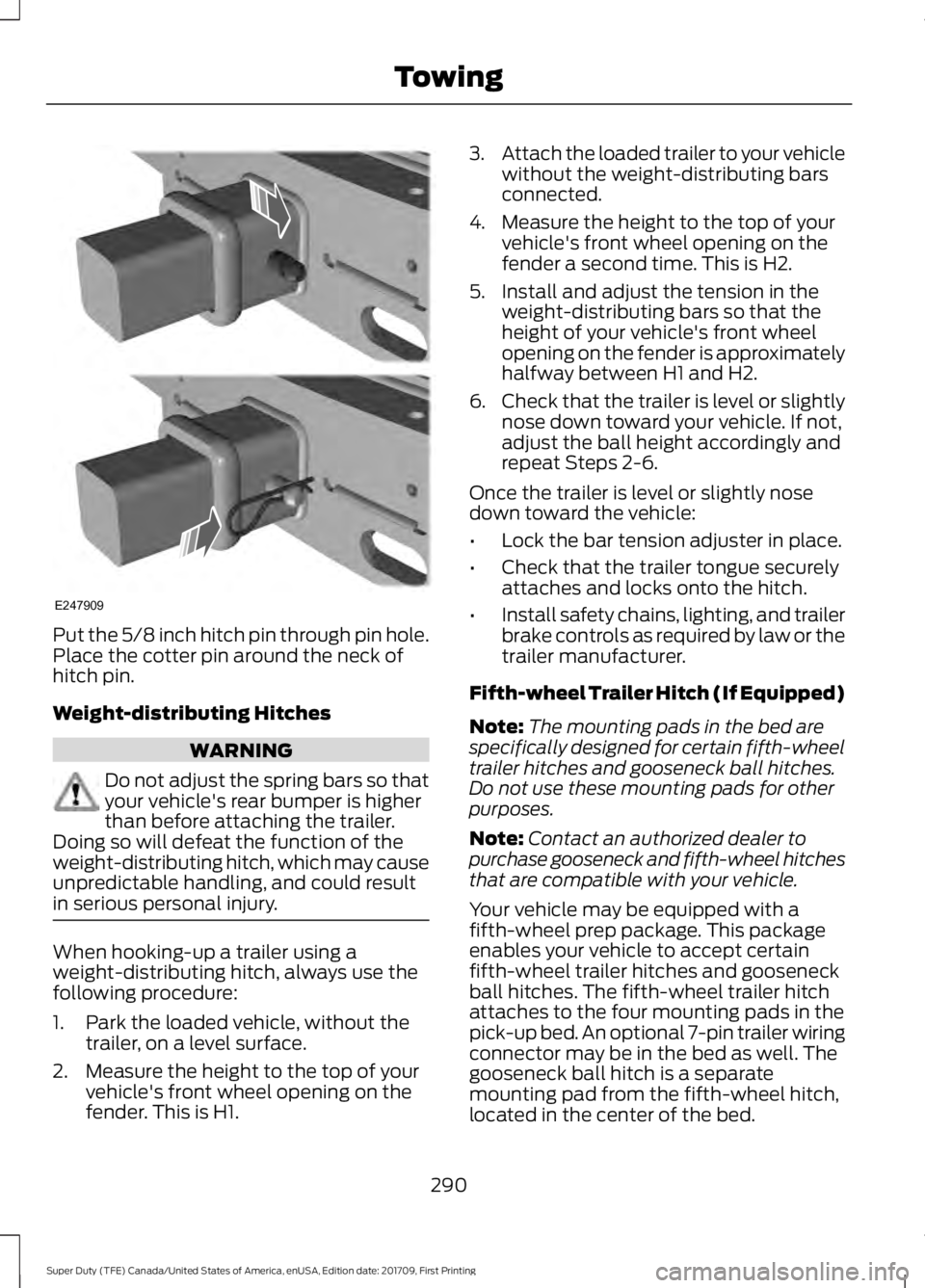
Put the 5/8 inch hitch pin through pin hole.
Place the cotter pin around the neck of
hitch pin.
Weight-distributing Hitches
WARNING
Do not adjust the spring bars so that
your vehicle's rear bumper is higher
than before attaching the trailer.
Doing so will defeat the function of the
weight-distributing hitch, which may cause
unpredictable handling, and could result
in serious personal injury. When hooking-up a trailer using a
weight-distributing hitch, always use the
following procedure:
1. Park the loaded vehicle, without the
trailer, on a level surface.
2. Measure the height to the top of your vehicle's front wheel opening on the
fender. This is H1. 3.
Attach the loaded trailer to your vehicle
without the weight-distributing bars
connected.
4. Measure the height to the top of your vehicle's front wheel opening on the
fender a second time. This is H2.
5. Install and adjust the tension in the weight-distributing bars so that the
height of your vehicle's front wheel
opening on the fender is approximately
halfway between H1 and H2.
6. Check that the trailer is level or slightly
nose down toward your vehicle. If not,
adjust the ball height accordingly and
repeat Steps 2-6.
Once the trailer is level or slightly nose
down toward the vehicle:
• Lock the bar tension adjuster in place.
• Check that the trailer tongue securely
attaches and locks onto the hitch.
• Install safety chains, lighting, and trailer
brake controls as required by law or the
trailer manufacturer.
Fifth-wheel Trailer Hitch (If Equipped)
Note: The mounting pads in the bed are
specifically designed for certain fifth-wheel
trailer hitches and gooseneck ball hitches.
Do not use these mounting pads for other
purposes.
Note: Contact an authorized dealer to
purchase gooseneck and fifth-wheel hitches
that are compatible with your vehicle.
Your vehicle may be equipped with a
fifth-wheel prep package. This package
enables your vehicle to accept certain
fifth-wheel trailer hitches and gooseneck
ball hitches. The fifth-wheel trailer hitch
attaches to the four mounting pads in the
pick-up bed. An optional 7-pin trailer wiring
connector may be in the bed as well. The
gooseneck ball hitch is a separate
mounting pad from the fifth-wheel hitch,
located in the center of the bed.
290
Super Duty (TFE) Canada/United States of America, enUSA, Edition date: 201709, First Printing TowingE247909
Page 300 of 656
Four-wheel Drive Vehicles Equipped
with a Manual-shift Transfer Case
1. Put the transmission in neutral (N).
2. Put the transfer case in neutral (N).
3.
Put the hub locks in the FREE position.
Always make sure that both hub locks
are set to the same position.
Four-wheel Drive Vehicles Equipped
with an Electronic-shift Transfer Case
Only tow a four-wheel drive vehicle that
has an electronic-shift transfer case with
all wheels on the ground. To do this, place
the transfer case in its neutral position and
engage the four-wheel-down towing
feature.
Perform the steps in the following section
after positioning your vehicle behind the
tow vehicle and properly securing them
together.
Note: Make sure you properly secure your
vehicle to the tow vehicle.
Four-wheel-down Towing
1. Put the ignition in the on position, but do not start the engine. If your vehicle
has an ignition key, turn the key to on.
If your vehicle has intelligent access,
press the engine START/STOP button
once without pressing the brake pedal.
2. Press and hold the brake pedal.
3. Rotate the four-wheel drive switch to 2H.
4. Shift the transmission to neutral (N).
5. Rotate the four-wheel drive switch from
2H to 4L and back to 2H five
times within seven seconds.
Note: If completed successfully, the
information display shows a message
indicating that your vehicle is safe to tow
with all wheels on the ground. Note:
If you do not see the message in the
display, you must perform the procedure
again from the beginning.
Note: You may hear an audible noise as the
transfer case shifts into its neutral position.
This is normal.
6. Leave the transmission in neutral (N) and turn the ignition as far as it will go
toward the off position (it will not turn
fully off when the transmission is in
neutral). If your vehicle has an ignition
key, you must leave the key in the
ignition while towing. To lock and
unlock your vehicle, use the keyless
entry keypad or extra set of keys. If your
vehicle has intelligent access, press the
engine
START/STOP button once
without pressing the brake pedal. You
do not need to leave your keys in the
vehicle. You can lock and unlock your
vehicle as you normally do.
7. Release the brake pedal. WARNINGS
Do not disconnect the battery during
recreational towing. It prevents the
transfer case from shifting properly
and may cause the vehicle to roll, even if
the transmission is in park (P). Shifting the transfer case to its
neutral position for recreational
towing may cause the vehicle to roll,
even if the transmission is in park (P). It
may injure the driver and others. Make sure
you press the foot brake and the vehicle is
in a secure, safe position when you shift to
neutral (N). Note:
Failing to put the transfer case in its
neutral position while towing with all four
wheels on the ground will damage vehicle
components.
297
Super Duty (TFE) Canada/United States of America, enUSA, Edition date: 201709, First Printing Towing
Page 301 of 656
Note:
You can check four-wheel-down
towing status at any time by opening the
driver's door or turning the ignition to the
accessory or on position and verifying a
message displays in the cluster.
To exit four-wheel-down towing and return
the transfer case to its 2H position:
1. With your vehicle still properly secured
to the tow vehicle, put the ignition in
the on position, but do not start the
engine. If your vehicle has an ignition
key, switch the key to on. If your vehicle
has intelligent access, press the engine
START/STOP
button once without
pressing the brake pedal.
2. Press and hold the brake pedal.
3. Shift the transmission out of neutral (N) and into any other gear.
4. Release the brake pedal.
Note: If completed successfully, the
2H
indicator light illuminates and a
confirmation message displays in the
instrument cluster.
Note: If the indicator light and message do
not display, you must perform the procedure
again from the beginning.
Note: You may hear an audible noise as the
transfer case shifts out of its neutral
position. This is normal.
Note: If a message displays in the
instrument cluster stating there is a shift
delay, transfer case gear tooth blockage
may be present. See
Resolving the Shift
Delay Issue after this section.
5. Apply the parking brake and disconnect
the vehicle from the tow vehicle.
6. Release the parking brake, start the engine and shift the transmission to
drive (D) to make sure the transfer
case is out of neutral (N). 7. If the transfer case does not
successfully shift out of neutral (N),
set the parking brake until you can have
your vehicle serviced.
Resolving the Shift Delay Issue
If the instrument cluster displays a shift
delay message, See
Information
Messages (page 131). You need to
perform the following steps:
1. Press and hold the brake pedal.
2. Put the transmission into neutral (N), and then start the engine.
3. With the engine running, shift the transmission to drive (D) and let the
vehicle roll forward, up to
3 ft (1 m).
You may hear an audible noise as the
transfer case shifts out of its neutral
position. This is normal.
4. When the issue is resolved, the instrument cluster displays a message
stating neutral tow is disabled.
298
Super Duty (TFE) Canada/United States of America, enUSA, Edition date: 201709, First Printing Towing