2018 FORD F-450 towing
[x] Cancel search: towingPage 284 of 660
remove the sticker from its current
location if the obstruction cannot
be cleared. Place a new sticker that
is visible to the camera in all
positions of the trailer behind your
vehicle.
• You can change your sticker
location by going into the trailer
menu, selecting trailer options,
selecting change trailer settings
and then selecting the change
sticker option. The previous sticker
must be removed. ONLY ONE
STICKER SHOULD BE PLACED
ON THE TRAILER FOR CORRECT
SYSTEM FUNCTION.
• The camera system uses the
entered measurements to help
locate the sticker. Inaccurate
measurements reduce the system ’s
ability to locate the sticker. Check
the measurements entered into the
system are correct. Refer to the
step 4 of trailer reverse guidance
setup for instructions on
measurements.
• You can change your measurement
by going into the trailer menu,
selecting trailer options, selecting
change trailer setting and then
selecting the change sticker option.
Disregard the prompt to remove
this sticker and continue to the next
step if you only plan to update the
measurements for the current
sticker location.
System does not backup straight:
• Factors such as the drawbar
connection to the hitch receiver, road
camber, road grade and compliance in
the trailer suspension can influence
how straight the system is able to
reverse your trailer when the wheel is
not turned. You can compensate for
the trailer drifting to the right or left by slowly turning the wheel until the trailer
is following your desired path and then
holding the wheel in that position. If
you would like to recalibrate the
system for straight backing, you can do
so with the following procedure.
•
Go into the trailer menu, select
trailer options, select change trailer
setting and then select the change
sticker option. Your saved
measurements show. Do not
change them, but continue to
confirm measurements. Once you
confirm the measurements, the
system then prompts you to
perform the calibration procedure.
Note: The system is designed to be used
with the same trailer connection every time
the trailer is chosen from the selection
menu. Using a different drawbar or a
different pin hole, on drawbars with more
than one pin hole, when connecting the
drawbar to your vehicle affects the trailer
measurements. Take the measurements
again and update if required.
TRAILER SWAY CONTROL (If
Equipped) WARNING
Turning off trailer sway control
increases the risk of loss of vehicle
control, serious injury or death. Ford
does not recommend disabling this feature
except in situations where speed reduction
may be detrimental (such as hill climbing),
the driver has significant trailer towing
experience, and can control trailer sway
and maintain safe operation. Note:
This feature does not prevent trailer
sway, but reduces it once it begins.
Note: This feature cannot stop all trailers
from swaying.
281
Super Duty (TFE) Canada/United States of America, enUSA, Edition date: 201709, Second Printing Towing
Page 285 of 660
Note:
In some cases, if vehicle speed is too
high, the system may activate multiple
times, gradually reducing vehicle speed.
This feature applies your vehicle brakes at
individual wheels and, if necessary, reduces
engine power. If the trailer begins to sway,
the stability control light flashes and the
message TRAILER SWAY REDUCE
SPEED appears in the information display.
The first thing to do is slow your vehicle
down, then pull safely to the side of the
road and check for proper tongue load and
trailer load distribution. See
Load
Carrying (page 264).
RECOMMENDED TOWING
WEIGHTS WARNING
You must use the heavy-duty
drawbar pin supplied with
your vehicle when using the
heavy-duty hitch. Failure to follow
this instruction could result in the
loss of control of your vehicle,
personal injury or death. Note:
Vehicles with a heavy-duty
hitch must use the drawbar pin
stamped 21,000 LBS. You can
obtain a replacement drawbar pin
at your authorized dealer. Note:
Make sure to take into
consideration trailer frontal area.
Do not exceed 60 ft 2
(5.6 m 2
) trailer
frontal area for conventional
trailers. Do not exceed 75 ft 2
(6.9
m 2
) trailer frontal area for fifth
wheel and gooseneck trailers.
Note: Exceeding this limitation
may significantly reduce the
performance of your towing
vehicle. Selecting a trailer with a
low aerodynamic drag and rounded
front design helps optimize
performance and fuel economy.
Note: For high altitude operation,
reduce the gross combined weight
by 2% per
1,000 ft (300 m)
starting at the 1,000 ft (300 m)
elevation point.
Note: Certain states require
electric trailer brakes for trailers
over a specified weight. Be sure to
check state regulations for this
specified weight. The maximum
trailer weights listed may be limited
to this specified weight, as your
vehicle's electrical system may not
include the wiring connector
needed to use electric trailer
brakes.
Your vehicle may tow a trailer
provided the maximum trailer
weight is less than or equal to the
maximum trailer weight
calculated using the formula
following the chart.
282
Super Duty (TFE) Canada/United States of America, enUSA, Edition date: 201709, Second Printing Towing
Page 286 of 660
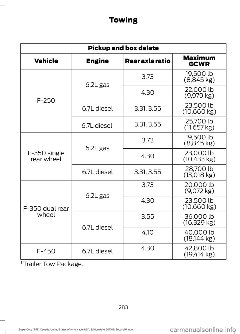
Pickup and box delete
MaximumGCWR
Rear axle ratio
Engine
Vehicle
19,500 lb
(8,845 kg)
3.73
6.2L gas
F-250 22,000 lb
(9,979 kg)
4.30
23,500 lb
(10,660 kg)
3.31, 3.55
6.7L diesel
25,700 lb
(11,657 kg)
3.31, 3.55
6.7L diesel 1
19,500 lb
(8,845 kg)
3.73
6.2L gas
F-350 single
rear wheel 23,000 lb
(10,433 kg)
4.30
28,700 lb
(13,018 kg)
3.31, 3.55
6.7L diesel
20,000 lb
(9,072 kg)
3.73
6.2L gas
F-350 dual rear wheel 23,500 lb
(10,660 kg)
4.30
36,000 lb
(16,329 kg)
3.55
6.7L diesel 40,000 lb
(18,144 kg)
4.10
42,800 lb
(19,414 kg)
4.30
6.7L diesel
F-450
1 Trailer Tow Package.
283
Super Duty (TFE) Canada/United States of America, enUSA, Edition date: 201709, Second Printing Towing
Page 287 of 660
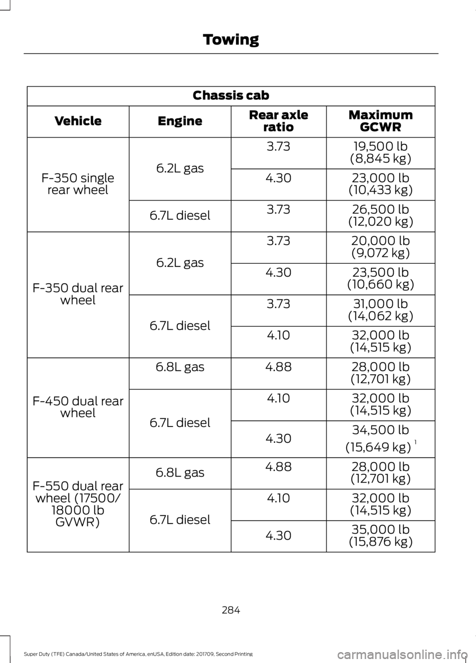
Chassis cab
MaximumGCWR
Rear axle
ratio
Engine
Vehicle
19,500 lb
(8,845 kg)
3.73
6.2L gas
F-350 single
rear wheel 23,000 lb
(10,433 kg)
4.30
26,500 lb
(12,020 kg)
3.73
6.7L diesel
20,000 lb
(9,072 kg)
3.73
6.2L gas
F-350 dual rear wheel 23,500 lb
(10,660 kg)
4.30
31,000 lb
(14,062 kg)
3.73
6.7L diesel 32,000 lb
(14,515 kg)
4.10
28,000 lb
(12,701 kg)
4.88
6.8L gas
F-450 dual rear wheel 32,000 lb
(14,515 kg)
4.10
6.7L diesel 34,500 lb
(15,649 kg) 1
4.30
28,000 lb
(12,701 kg)
4.88
6.8L gas
F-550 dual rear wheel (17500/ 18000 lbGVWR) 32,000 lb
(14,515 kg)
4.10
6.7L diesel 35,000 lb
(15,876 kg)
4.30
284
Super Duty (TFE) Canada/United States of America, enUSA, Edition date: 201709, Second Printing Towing
Page 288 of 660
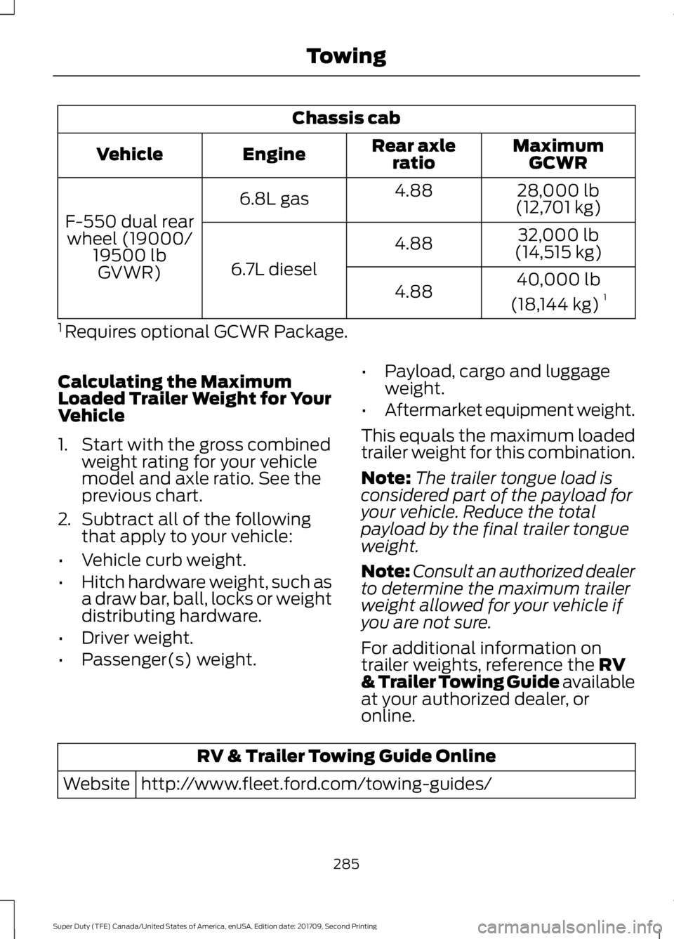
Chassis cab
MaximumGCWR
Rear axle
ratio
Engine
Vehicle
28,000 lb
(12,701 kg)
4.88
6.8L gas
F-550 dual rear wheel (19000/ 19500 lbGVWR) 32,000 lb
(14,515 kg)
4.88
6.7L diesel 40,000 lb
(18,144 kg) 1
4.88
1 Requires optional GCWR Package.
Calculating the Maximum
Loaded Trailer Weight for Your
Vehicle
1. Start with the gross combined weight rating for your vehicle
model and axle ratio. See the
previous chart.
2. Subtract all of the following
that apply to your vehicle:
• Vehicle curb weight.
• Hitch hardware weight, such as
a draw bar, ball, locks or weight
distributing hardware.
• Driver weight.
• Passenger(s) weight. •
Payload, cargo and luggage
weight.
• Aftermarket equipment weight.
This equals the maximum loaded
trailer weight for this combination.
Note: The trailer tongue load is
considered part of the payload for
your vehicle. Reduce the total
payload by the final trailer tongue
weight.
Note: Consult an authorized dealer
to determine the maximum trailer
weight allowed for your vehicle if
you are not sure.
For additional information on
trailer weights, reference the RV
& Trailer Towing Guide available
at your authorized dealer, or
online. RV & Trailer Towing Guide Online
http://www.fleet.ford.com/towing-guides/
Website
285
Super Duty (TFE) Canada/United States of America, enUSA, Edition date: 201709, Second Printing Towing
Page 289 of 660

ESSENTIAL TOWING CHECKS
WARNING
Do not exceed the maximum vertical
load on the tow ball. Failure to follow
this instruction could result in the
loss of control of your vehicle, personal
injury or death. Follow these guidelines for safe towing:
•
Do not tow a trailer until you drive your
vehicle at least 1,000 mi (1,600 km).
• Consult your local motor vehicle laws
for towing a trailer.
• See the instructions included with
towing accessories for the proper
installation and adjustment
specifications.
• Service your vehicle more frequently if
you tow a trailer. See your scheduled
maintenance information.
See
Scheduled Maintenance (page 581).
• If you use a rental trailer, follow the
instructions the rental agency gives
you.
See
Load Limits in the Load Carrying
chapter for load specification terms found
on the tire label and Safety Compliance
label and instructions on calculating your
vehicle's load.
Vehicles with a diesel engine have an
engine braking feature.
See General
Information (page 225).
Remember to account for the trailer
tongue weight as part of your vehicle load
when calculating the total vehicle weight.
Some vehicles will have the ability to
modify trailer towing features. See
General Information
(page 113). Trailer Towing Connector
When attaching the trailer wiring connector
to your vehicle, only use a proper fitting
connector that works with the vehicle and
trailer functions. Some seven-position
connectors may have the SAE J2863 logo,
which confirms that it is the proper wiring
connector and works correctly with your
vehicle.
Function
Color
Left turn signal and stop lamp
Yellow
Ground (-)
White
Electric brakes
Blue
Right turn signal and stop
lamp
Green
Battery (+)
Orange
Running lights
Brown
Reverse lights
Grey
286
Super Duty (TFE) Canada/United States of America, enUSA, Edition date: 201709, Second Printing TowingE163167
Page 290 of 660

Note:
If your vehicle is equipped with a
factory brake controller, the Battery (+)
Orange wire is powered when you start the
engine and you apply the brakes at least
once when a trailer with brake lamps is
connected. If your vehicle is not equipped
with a factory brake controller, relays control
the system and it becomes active when you
power on your vehicle.
Dynamic Hitching Using the Rear
View Camera System
Note: Active guidelines and fixed guidelines
are only available when the transmission is
in reverse (R).
Use the centerline (B) guideline to assist
you in setting your steering wheel properly
to help align the trailer hitch and tongue. Active guidelines.
A
Centerline.
B
Fixed guideline: Green zone.
C
Fixed guideline: Yellow zone.
D
Fixed guideline: Red zone.
E
Rear bumper.
F
Fixed guidelines are always shown in the
display, but the active guidelines only
display when the steering wheel is turned.
To use active guidelines, turn the steering
wheel to point the guidelines toward an
intended path. If the steering wheel
position is changed while reversing, your
vehicle might deviate from the original
intended path.
287
Super Duty (TFE) Canada/United States of America, enUSA, Edition date: 201709, Second Printing TowingABCD
F
E
E142436
Page 291 of 660

The active guidelines fade in and out
depending on the steering wheel position.
The active guidelines are not shown when
the steering wheel position is straight.
Always use caution while reversing.
Objects in the red zone are closest to your
vehicle and objects in the green zone are
farther away. Objects are getting closer to
your vehicle as they move from the green
zone to the yellow or red zones. Use the
side view mirrors and rear view mirror to
get better coverage on both sides and rear
of your vehicle.
Refer to the Rear View Camera section for
additional information. See Rear View
Camera (page 236).
Hitches
Note: On pick-up trucks, the trailer hitch
provided on this vehicle enhances crash
protection for the fuel system. Do not
remove!
Note: Do not cut, drill, weld or modify trailer
hitches. Modifying trailer hitches can reduce
hitch rating.
Do not use a hitch that either clamps onto
the bumper or attaches to the axle. You
must distribute the load in your trailer so
that 10-15% for conventional towing or
15-25% for fifth wheel towing of the total
weight of the trailer is on the tongue.
Hitch Components (If Equipped)
The following components are required.
Some are provided in certain vehicles.
• A trailer hitch with a 3 inch receiver and
5/8 inch hitch pin rated to tow up to
21,000 lb (9,525 kg)
.
• A hitch pin sleeve stored in the glove
box to be used when mounting the 3
inch drawbar.
• A cotter pin to help keep the hitch pin
in place. Installing a 3 Inch Drawbar with 3/4
Inch Pin Hole
The pin sleeve should be inserted in the
3/4 inch pin hole of the 3 inch drawbar.
Remove reducers before inserting the 3
inch drawbar. Insert the drawbar into hitch
receiver.
288
Super Duty (TFE) Canada/United States of America, enUSA, Edition date: 201709, Second Printing TowingE247903 E247902