2018 FORD F-150 key
[x] Cancel search: keyPage 326 of 641

If your vehicle has a key system:
1. Switch off the ignition.
2. Switch to start position.
3. Switch off the ignition.
4.
Switch on the ignition to re-enable the
fuel pump.
5. If the vehicle does not start, repeat steps 1 through 4.
If your vehicle has a push button start
system:
1. Press START/STOP to switch off your
vehicle.
2. Press the brake pedal and START/STOP
to switch on your
vehicle.
3. Remove your foot from the brake pedal
and press
START/STOP to switch off
your vehicle.
4. You can attempt to start the vehicle by pressing the brake pedal and
START/STOP
, or press START/STOP
without pressing the brake pedal.
5. If the vehicle does not start, repeat steps 1 through 4.
JUMP STARTING THE VEHICLE WARNING:
Batteries normally
produce explosive gases which can
cause personal injury. Therefore, do not
allow flames, sparks or lighted
substances to come near the battery.
When working near the battery, always
shield your face and protect your eyes.
Always provide correct ventilation. WARNING:
Keep batteries out of
reach of children. Batteries contain
sulfuric acid. Avoid contact with skin,
eyes or clothing. Shield your eyes when
working near the battery to protect
against possible splashing of acid
solution. In case of acid contact with skin
or eyes, flush immediately with water for
a minimum of 15 minutes and get prompt
medical attention. If acid is swallowed,
call a physician immediately. WARNING:
Use only adequately
sized cables with insulated clamps.
Preparing Your Vehicle
Do not attempt to push-start your
automatic transmission vehicle.
Note: Attempting to push-start a vehicle
with an automatic transmission may cause
transmission damage.
Note: Use only a 12-volt supply to start your
vehicle.
Note: Do not disconnect the battery of the
disabled vehicle as this could damage the
vehicle electrical system.
Park the booster vehicle close to the hood
of the disabled vehicle, making sure the
two vehicles do not touch.
Connecting the Jumper Cables WARNING:
Do not attach the
cables to fuel lines, engine rocker covers,
the intake manifold or electrical
components as grounding points. Stay
clear of moving parts. To avoid reverse
polarity connections, make sure that you
correctly identify the positive (+) and
negative (-) terminals on both the
disabled and booster vehicles before
connecting the cables.
323
F-150 (TFC) Canada/United States of America, enUSA, Edition date: 201709, Fifth-Printing Roadside Emergencies
Page 345 of 641

Protected Components
Fuse Rating
Fuse Number
Extended power module (Base only).
10A
9
Embedded modem module.
5A
10
Combined sensor module.
5A
11
Climate head module.
7.5A
12
Smart datalink connector.
Cluster.
7.5A
13
Steering column control module.
Brake on/off switch.
10A
14
Smart datalink connector.
10A
15
Tailgate release.
15A
16
Heads up display.
5A
17
Terrain switch.
Ignition switch and passive-entry passive-
start start stop switch.
5A
18
Key inhibit solenoid.
Extended power module (except Raptor).
7.5A
19
Restraint control module (Raptor only).
7.5A
Not used.
—
20
Heads up display.
5A
21
In car temperature with humidity sensor.
Passenger occupant detection. (Raptor
only)
5A
22
Power driven rear glass switch.
10A
23
Inverter.
Driver side window.
Moonroof.
Vista roof.
Central lock/unlock.
20A
24
Driver door control module.
30A
25
Passenger door control module.
30A
26
Vista roof.
30A
27
Moonroof.
342
F-150 (TFC) Canada/United States of America, enUSA, Edition date: 201709, Fifth-Printing Fuses
Page 363 of 641

DRAINING THE FUEL FILTER
WATER TRAP
WARNING: Do not dispose of fuel
in the household refuse or the public
sewage system. Use an authorized waste
disposal facility.
Note: Only add fuel that meets the Ford
specification. See
Fuel Quality (page 187).
Note: The in-tank pump will turn off
automatically after approximately 30
seconds.
The fuel water trap is above the frame rail
under the driver side of the vehicle. Front of Vehicle.
A
1. Switch the ignition off.
2. Loosen the drain plug approximately one and a half turns.
3. Allow the water to drain.
4. Tighten the drain plug until you feel a strong resistance.
5. Key on for 30 seconds then key off. Repeat twice.
6. Start the engine.
7. Check for leaks. Note:
The water-in-fuel indicator lamp will
go out after approximately 2 seconds, with
the engine running.
FUEL FILTER - DIESEL
Your fuel filters must be changed at the
correct service interval or when you see the
low fuel pressure message appear. See
Scheduled Maintenance
(page 561).
FUEL FILTER - GASOLINE
Your vehicle is equipped with a lifetime
fuel filter that is integrated with the fuel
tank. Regular maintenance or replacement
is not needed.
CHANGING THE 12V BATTERY WARNING:
Batteries normally
produce explosive gases which can
cause personal injury. Therefore, do not
allow flames, sparks or lighted
substances to come near the battery.
When working near the battery, always
shield your face and protect your eyes.
Always provide correct ventilation. WARNING:
When lifting a
plastic-cased battery, excessive pressure
on the end walls could cause acid to flow
through the vent caps, resulting in
personal injury and damage to the
vehicle or battery. Lift the battery with a
battery carrier or with your hands on
opposite corners.
360
F-150 (TFC) Canada/United States of America, enUSA, Edition date: 201709, Fifth-Printing MaintenanceE254226
Page 407 of 641

System reset tips:
•
To reduce the chances of interference
from another vehicle, perform the
system reset procedure at least three
feet, one meter, away from another
Ford Motor Company vehicle
undergoing the system reset procedure
at the same time.
• Do not wait more than two minutes
between resetting each tire sensor or
the system can time-out and you need
to repeat the entire procedure on all
four wheels.
• A double horn sounds indicating the
need to repeat the procedure.
Performing the System Reset Procedure
Read the entire procedure before
attempting.
1. Drive the vehicle above 20 mph
(32 km/h) for at least two minutes,
then park in a safe location where you
can easily get to all four tires and have
access to an air pump.
2. Place the ignition in the off position and
keep the key in the ignition.
3. Cycle the ignition to the on position with the engine off.
4. Switch the hazard flashers on then off three times. You must accomplish this
within 10 seconds. If you successfully
enter the reset mode, the horn sounds
once, the system indicator flashes and
a message shows in the information
display. If this does not occur, please
try again starting at Step 2. If after
repeated attempts to enter the reset
mode, the horn does not sound, the
system indicator does not flash and no
message shows in the information
display, seek service from your
authorized dealer. 5. Train the tire pressure monitoring
system sensors in the tires using the
following system reset sequence
starting with the left front tire in the
following clockwise order: Left front -
driver side front tire, Right front -
passenger side front tire, Right rear -
passenger side rear tire - Left rear,
driver side rear tire.
6. Remove the valve cap from the valve stem on the left front tire. Decrease the
air pressure until the horn sounds.
Note: The single horn tone confirms that
the sensor identification code has been
learned by the module for this position. If a
double horn is heard, the reset procedure
was unsuccessful, and you must repeat it.
7. Remove the valve cap from the valve stem on the right front tire. Decrease
the air pressure until the horn sounds.
8. Remove the valve cap from the valve stem on the right rear tire. Decrease the
air pressure until the horn sounds.
9. Remove the valve cap from the valve stem on the left rear tire. Decrease the
air pressure until the horn sounds.
Training is complete after the horn
sounds for the last tire trained, driver
side rear tire, the system indicator
stops flashing, and a message shows
in the information display.
10. Turn the ignition off. If two short horn
beeps are heard, the reset procedure
was unsuccessful and you must
repeat it. If after repeating the
procedure and two short beeps are
heard when the ignition is turned to
off, seek assistance from your
authorized dealer.
404
F-150 (TFC) Canada/United States of America, enUSA, Edition date: 201709, Fifth-Printing Wheels and Tires
Page 411 of 641

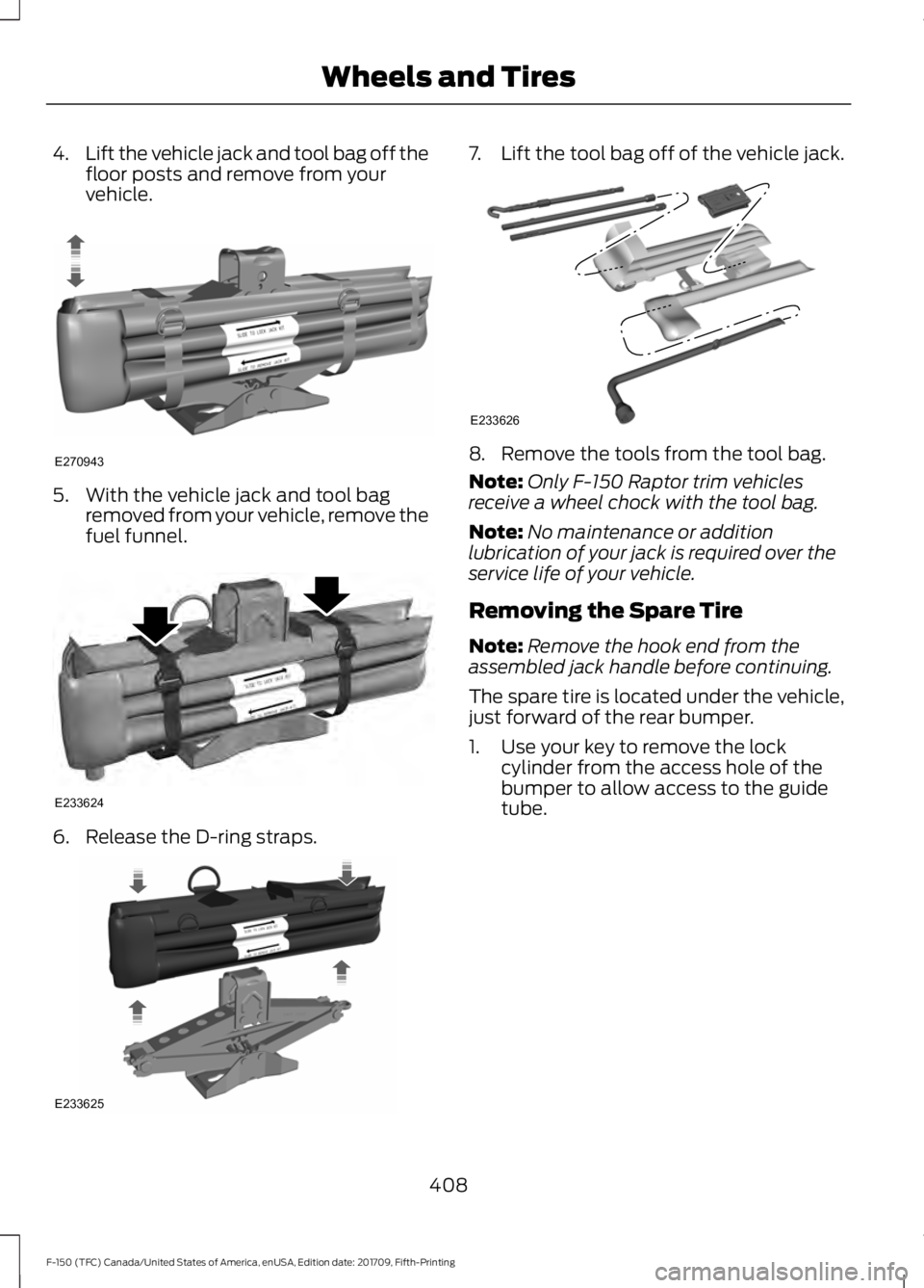
4.
Lift the vehicle jack and tool bag off the
floor posts and remove from your
vehicle. 5. With the vehicle jack and tool bag
removed from your vehicle, remove the
fuel funnel. 6. Release the D-ring straps. 7.
Lift the tool bag off of the vehicle jack. 8. Remove the tools from the tool bag.
Note:
Only F-150 Raptor trim vehicles
receive a wheel chock with the tool bag.
Note: No maintenance or addition
lubrication of your jack is required over the
service life of your vehicle.
Removing the Spare Tire
Note: Remove the hook end from the
assembled jack handle before continuing.
The spare tire is located under the vehicle,
just forward of the rear bumper.
1. Use your key to remove the lock cylinder from the access hole of the
bumper to allow access to the guide
tube.
408
F-150 (TFC) Canada/United States of America, enUSA, Edition date: 201709, Fifth-Printing Wheels and TiresE270943 E233624 E233625 E233626
Page 414 of 641

5. Remove the vehicle jack and fully
tighten the lug nuts in the order shown.
See Technical Specifications (page
413).
6. Stow the flat tire. See the Stowing the Flat or Spare Tire.
7. Stow the vehicle jack and lug wrench. Make sure the jack is securely fastened
before you drive. See Stowing the
Vehicle Jack and Tool Bag.
8. Unblock the wheels. Stowing the Flat or Spare Tire
Note:
Failure to follow the spare tire
stowage instructions may result in failure of
the cable or loss of the spare tire.
1. Lay the tire on the ground with the valve stem facing up.
2. Slide the wheel partially under the vehicle and install the retainer through
the wheel center. Pull on the cable to
align the components at the end of the
cable.
3. Turn the jack handle clockwise until the tire is raised to its stowed position
underneath the vehicle. The effort to
turn the jack handle increases
significantly and the spare tire carrier
ratchets or slips when the tire is raised
to the maximum tightness. Tighten to the best of your ability, to the point
where the ratchet or slip occurs, if
possible. The spare tire carrier does not
allow you to overtighten. If the spare
tire carrier ratchets or slips with little
effort, contact your authorized dealer.
4. Check that the tire lies flat against the frame and is properly tightened. Try to
push or pull, then turn the tire to be
sure it does not move. Loosen and
retighten, if necessary. Failure to
properly stow the spare tire may result
in failure of the winch cable and loss
of the tire.
5. Repeat this tightness check procedure
when servicing the spare tire pressure,
every six months, as per your scheduled
maintenance information, or at any
time that the spare tire is disturbed
through service of other components.
6. If removed, install the spare tire lock into the bumper drive tube with the
spare tire lock key and jack handle.
Stowing the Vehicle Jack and Tool
Bag 1. Adjust the jack up or down by rotating
the lead screw located on the end of
the jack. The stowage markings should
line up with the bottom channel.
411
F-150 (TFC) Canada/United States of America, enUSA, Edition date: 201709, Fifth-Printing Wheels and TiresE166719
1
3
5 4
6
2 E184021
Page 415 of 641

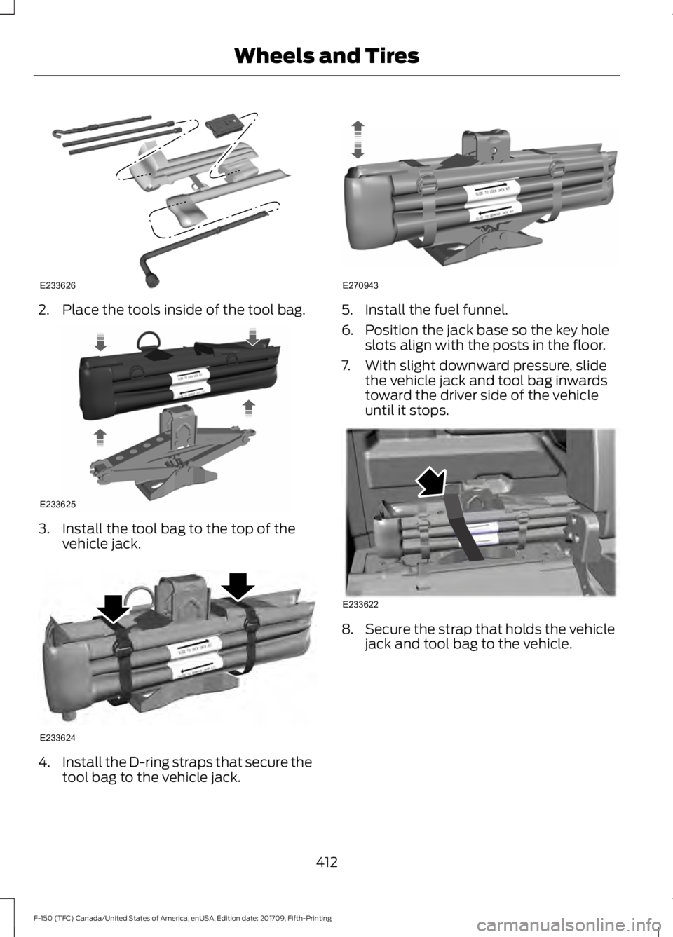
2. Place the tools inside of the tool bag.
3. Install the tool bag to the top of the
vehicle jack. 4.
Install the D-ring straps that secure the
tool bag to the vehicle jack. 5. Install the fuel funnel.
6. Position the jack base so the key hole
slots align with the posts in the floor.
7. With slight downward pressure, slide the vehicle jack and tool bag inwards
toward the driver side of the vehicle
until it stops. 8.
Secure the strap that holds the vehicle
jack and tool bag to the vehicle.
412
F-150 (TFC) Canada/United States of America, enUSA, Edition date: 201709, Fifth-Printing Wheels and TiresE233626 E233625 E233624 E270943 E233622
Page 464 of 641

Troubleshooting
Action
Condition
Message
No action required. This
message should disappear
shortly.
Radio requires more than
two seconds to produce
audio for the selected
channel.
Acquiring\b
If this message does not
clear shortly, or with an igni-
tion key cycle, your receiver
may have a fault. See an
authorized dealer for service.
There is an internal module
or system failure present.
Satellite antenna fault
SIRIUS system failure
Tune to another channel or
choose another preset.
The channel is no longer
available.
Invalid Channel
Contact SiriusXM at 1-888-
539-7474 to subscribe to
the channel, or tune to
another channel.
Your subscription does not
include this channel.
Unsubscribed Channel
The signal is blocked. When
you move into an open area,
the signal should return.
The signal is lost from the
SiriusXM satellite or Siri-
usXM tower to your vehicle
antenna.
No Signal
No action required. The
process may take up to
three minutes.
Update of channel
programming in progress.
Updating\b
Contact SiriusXM at 1-888-
539-7474 to resolve
subscription issues.
Your satellite service is no
longer available.
Questions? Call
1-888-539-7474
Use the channel guide to
turn off the Lock or Skip
function on that station.
All the channels in the
selected category are either
skipped or locked.
None found
Check Channel Guide
No action required.
SiriusXM has updated the
channels available for your
vehicle.
Subscription Updated
461
F-150 (TFC) Canada/United States of America, enUSA, Edition date: 201709, Fifth-Printing Audio System