2018 FORD EXPEDITION wheel
[x] Cancel search: wheelPage 269 of 571
For the short wheel base system, it is
necessary for the second panel located
toward the front of the vehicle to be raised
up when the seats are folded down.
For the long wheel base system, it is
necessary for the second panel located
toward the front of the vehicle to be raised
up.
Note:
Before moving the board into the
shelf position, you may need to flip down
the hooks.
Note: Do not put more than 50 lb (22 kg)
on shelf.
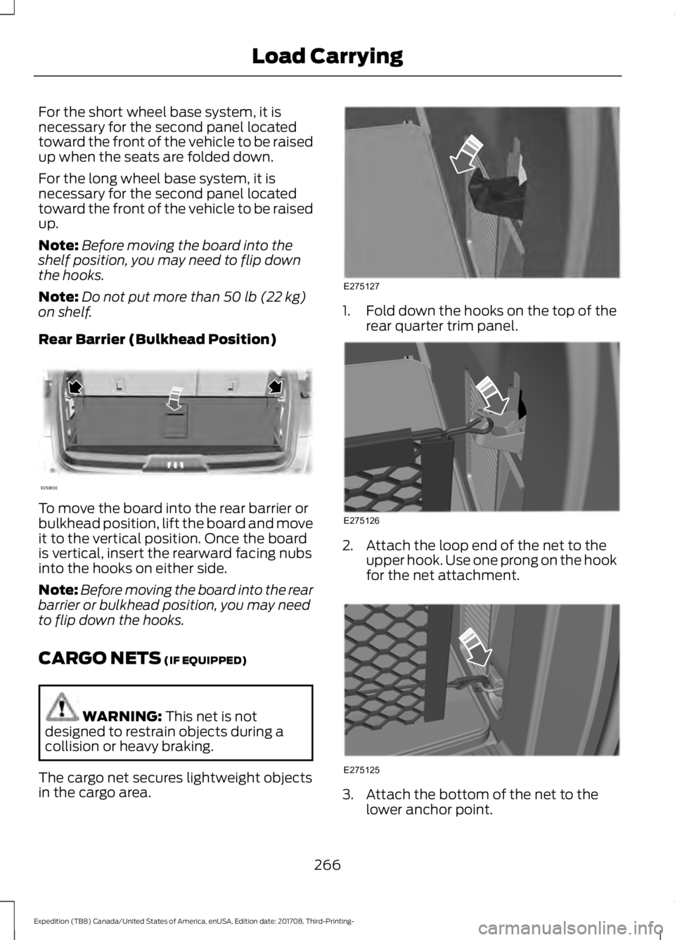
Rear Barrier (Bulkhead Position) To move the board into the rear barrier or
bulkhead position, lift the board and move
it to the vertical position. Once the board
is vertical, insert the rearward facing nubs
into the hooks on either side.
Note:
Before moving the board into the rear
barrier or bulkhead position, you may need
to flip down the hooks.
CARGO NETS
(IF EQUIPPED) WARNING:
This net is not
designed to restrain objects during a
collision or heavy braking.
The cargo net secures lightweight objects
in the cargo area. 1.
Fold down the hooks on the top of the
rear quarter trim panel. 2. Attach the loop end of the net to the
upper hook. Use one prong on the hook
for the net attachment. 3. Attach the bottom of the net to the
lower anchor point.
266
Expedition (TB8) Canada/United States of America, enUSA, Edition date: 201708, Third-Printing- Load CarryingE250830 E275127 E275126 E275125
Page 279 of 571
Step 1: Position your Vehicle and Trailer
Hitch your conventional trailer to your
vehicle. See Essential Towing Checks
(page 287).
Park your vehicle and hitched trailer on a
level surface.
For best results, make sure that your trailer
rides level with the ground when you hitch
it to your vehicle. More information on
selecting your towbar is available in the
Towing section.
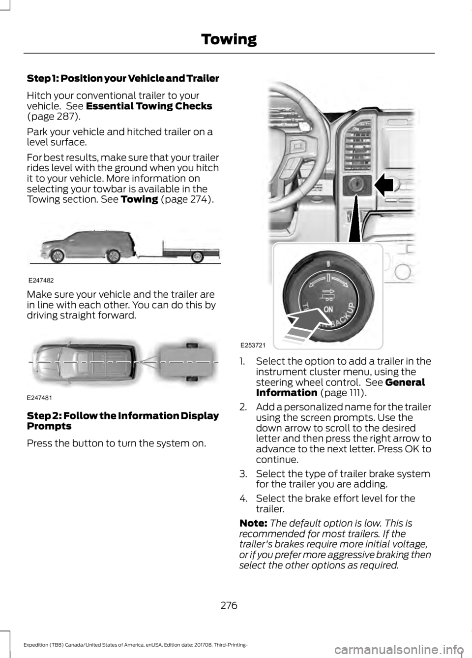
See Towing (page 274). Make sure your vehicle and the trailer are
in line with each other. You can do this by
driving straight forward.
Step 2: Follow the Information Display
Prompts
Press the button to turn the system on. 1.
Select the option to add a trailer in the
instrument cluster menu, using the
steering wheel control. See
General
Information (page 111).
2. Add a personalized name for the trailer
using the screen prompts. Use the
down arrow to scroll to the desired
letter and then press the right arrow to
advance to the next letter. Press OK to
continue.
3. Select the type of trailer brake system for the trailer you are adding.
4. Select the brake effort level for the trailer.
Note: The default option is low. This is
recommended for most trailers. If the
trailer's brakes require more initial voltage,
or if you prefer more aggressive braking then
select the other options as required.
276
Expedition (TB8) Canada/United States of America, enUSA, Edition date: 201708, Third-Printing- TowingE247482 E247481 E253721
Page 280 of 571
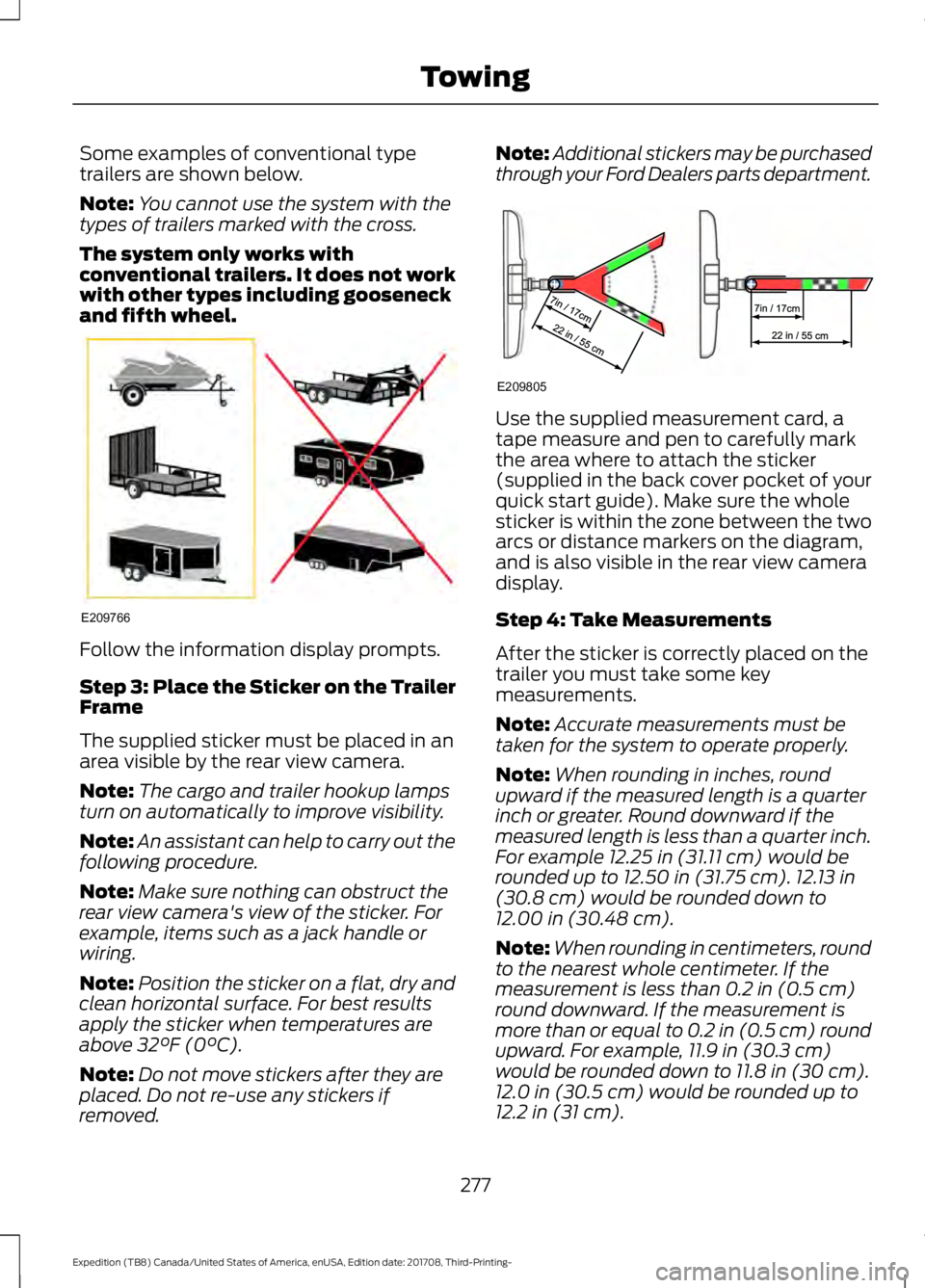
Some examples of conventional type
trailers are shown below.
Note:
You cannot use the system with the
types of trailers marked with the cross.
The system only works with
conventional trailers. It does not work
with other types including gooseneck
and fifth wheel. Follow the information display prompts.
Step 3: Place the Sticker on the Trailer
Frame
The supplied sticker must be placed in an
area visible by the rear view camera.
Note:
The cargo and trailer hookup lamps
turn on automatically to improve visibility.
Note: An assistant can help to carry out the
following procedure.
Note: Make sure nothing can obstruct the
rear view camera's view of the sticker. For
example, items such as a jack handle or
wiring.
Note: Position the sticker on a flat, dry and
clean horizontal surface. For best results
apply the sticker when temperatures are
above 32°F (0°C).
Note: Do not move stickers after they are
placed. Do not re-use any stickers if
removed. Note:
Additional stickers may be purchased
through your Ford Dealers parts department. Use the supplied measurement card, a
tape measure and pen to carefully mark
the area where to attach the sticker
(supplied in the back cover pocket of your
quick start guide). Make sure the whole
sticker is within the zone between the two
arcs or distance markers on the diagram,
and is also visible in the rear view camera
display.
Step 4: Take Measurements
After the sticker is correctly placed on the
trailer you must take some key
measurements.
Note:
Accurate measurements must be
taken for the system to operate properly.
Note: When rounding in inches, round
upward if the measured length is a quarter
inch or greater. Round downward if the
measured length is less than a quarter inch.
For example
12.25 in (31.11 cm) would be
rounded up to 12.50 in (31.75 cm). 12.13 in
(30.8 cm) would be rounded down to
12.00 in (30.48 cm).
Note: When rounding in centimeters, round
to the nearest whole centimeter. If the
measurement is less than
0.2 in (0.5 cm)
round downward. If the measurement is
more than or equal to 0.2 in (0.5 cm) round
upward. For example, 11.9 in (30.3 cm)
would be rounded down to
11.8 in (30 cm).
12.0 in (30.5 cm) would be rounded up to
12.2 in (31 cm).
277
Expedition (TB8) Canada/United States of America, enUSA, Edition date: 201708, Third-Printing- TowingE209766 E209805
Page 281 of 571
Note:
Use consistent metric or imperial
units as required by your country or vehicle.
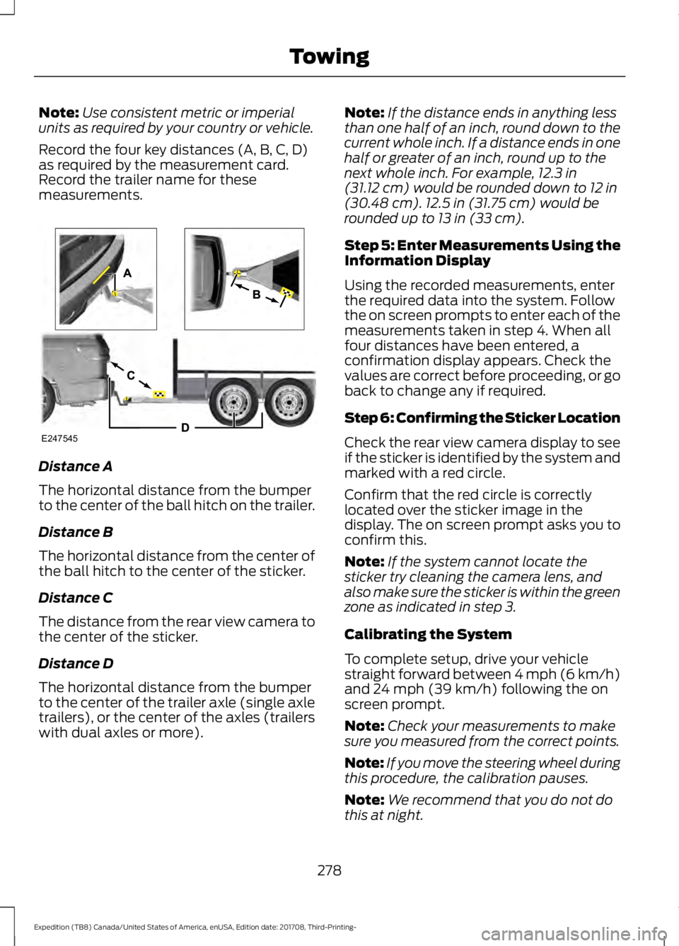
Record the four key distances (A, B, C, D)
as required by the measurement card.
Record the trailer name for these
measurements. Distance A
The horizontal distance from the bumper
to the center of the ball hitch on the trailer.
Distance B
The horizontal distance from the center of
the ball hitch to the center of the sticker.
Distance C
The distance from the rear view camera to
the center of the sticker.
Distance D
The horizontal distance from the bumper
to the center of the trailer axle (single axle
trailers), or the center of the axles (trailers
with dual axles or more). Note:
If the distance ends in anything less
than one half of an inch, round down to the
current whole inch. If a distance ends in one
half or greater of an inch, round up to the
next whole inch. For example, 12.3 in
(31.12 cm) would be rounded down to 12 in
(30.48 cm). 12.5 in (31.75 cm) would be
rounded up to 13 in (33 cm).
Step 5: Enter Measurements Using the
Information Display
Using the recorded measurements, enter
the required data into the system. Follow
the on screen prompts to enter each of the
measurements taken in step 4. When all
four distances have been entered, a
confirmation display appears. Check the
values are correct before proceeding, or go
back to change any if required.
Step 6: Confirming the Sticker Location
Check the rear view camera display to see
if the sticker is identified by the system and
marked with a red circle.
Confirm that the red circle is correctly
located over the sticker image in the
display. The on screen prompt asks you to
confirm this.
Note: If the system cannot locate the
sticker try cleaning the camera lens, and
also make sure the sticker is within the green
zone as indicated in step 3.
Calibrating the System
To complete setup, drive your vehicle
straight forward between 4 mph (6 km/h)
and
24 mph (39 km/h) following the on
screen prompt.
Note: Check your measurements to make
sure you measured from the correct points.
Note: If you move the steering wheel during
this procedure, the calibration pauses.
Note: We recommend that you do not do
this at night.
278
Expedition (TB8) Canada/United States of America, enUSA, Edition date: 201708, Third-Printing- TowingE247545
Page 282 of 571
A message displays during calibration and
after calibration is complete.
Using Pro Trailer Backup Assist
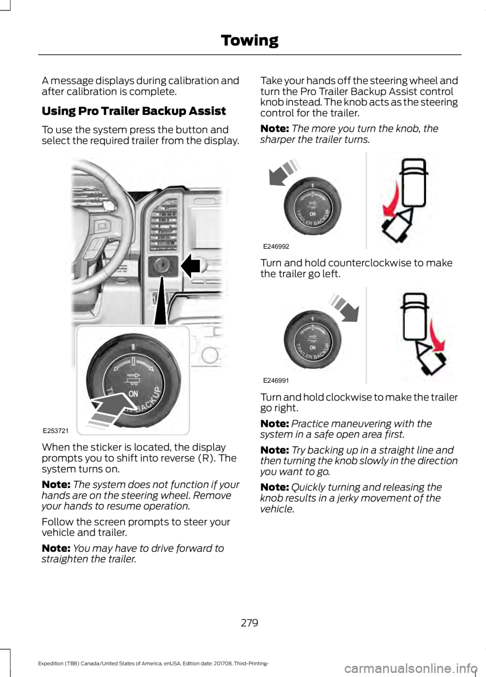
To use the system press the button and
select the required trailer from the display.
When the sticker is located, the display
prompts you to shift into reverse (R). The
system turns on.
Note:
The system does not function if your
hands are on the steering wheel. Remove
your hands to resume operation.
Follow the screen prompts to steer your
vehicle and trailer.
Note: You may have to drive forward to
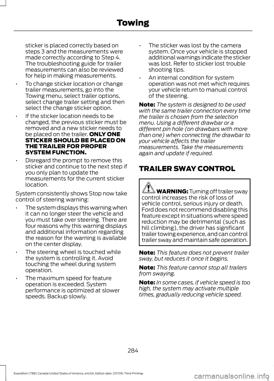
straighten the trailer. Take your hands off the steering wheel and
turn the Pro Trailer Backup Assist control
knob instead. The knob acts as the steering
control for the trailer.
Note:
The more you turn the knob, the
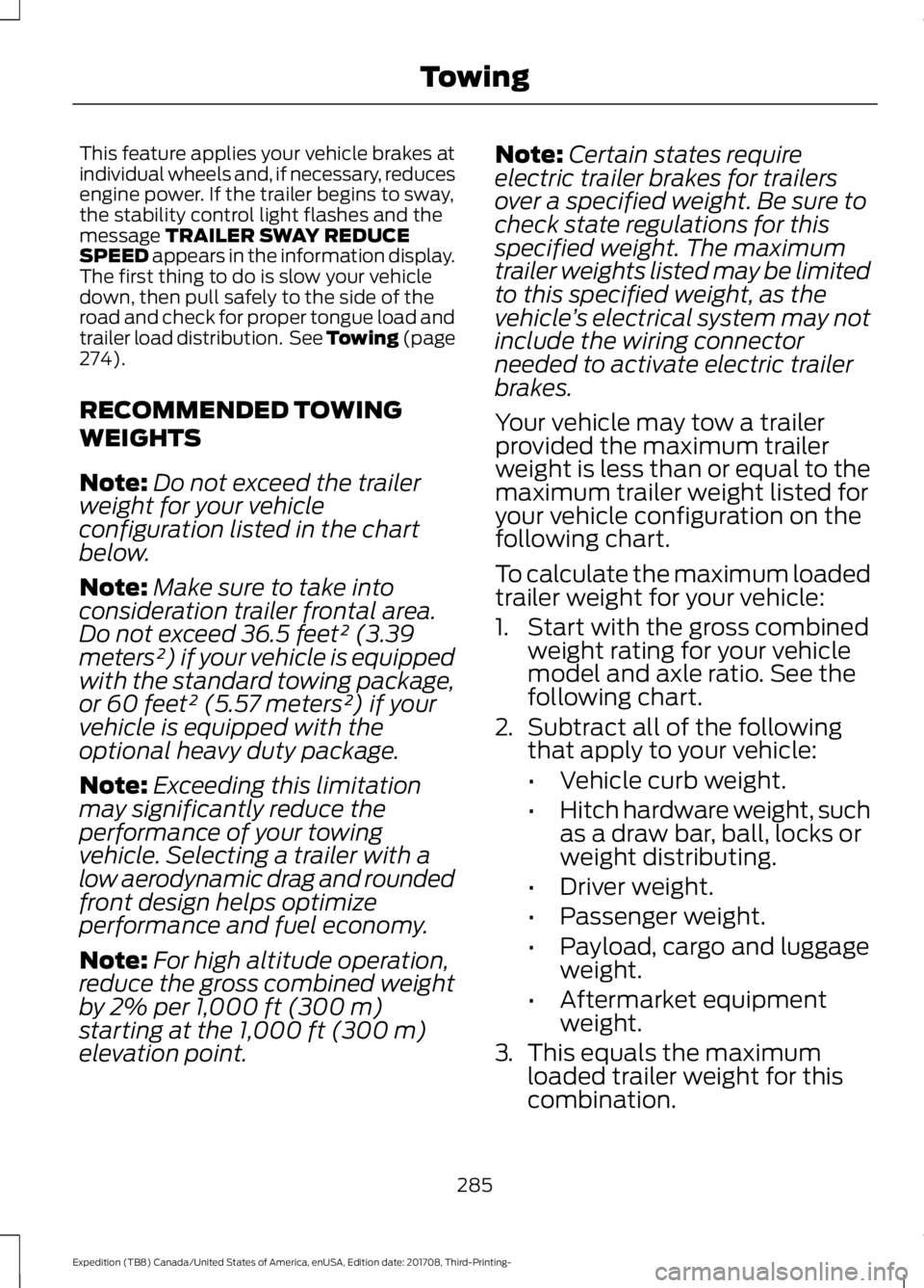
sharper the trailer turns. Turn and hold counterclockwise to make
the trailer go left.
Turn and hold clockwise to make the trailer
go right.
Note:
Practice maneuvering with the
system in a safe open area first.
Note: Try backing up in a straight line and
then turning the knob slowly in the direction
you want to go.
Note: Quickly turning and releasing the
knob results in a jerky movement of the
vehicle.
279
Expedition (TB8) Canada/United States of America, enUSA, Edition date: 201708, Third-Printing- TowingE253721 E246992 E246991
Page 287 of 571
sticker is placed correctly based on
steps 3 and the measurements were
made correctly according to Step 4.
The troubleshooting guide for trailer
measurements can also be reviewed
for help in making measurements.
• To change sticker location or change
trailer measurements, go into the
Towing menu, select trailer options,
select change trailer setting and then
select the change sticker option.
• If the sticker location needs to be
changed, the previous sticker must be
removed and a new sticker needs to
be placed on the trailer. ONLY ONE
STICKER SHOULD BE PLACED ON
THE TRAILER FOR PROPER
SYSTEM FUNCTION.
• Disregard the prompt to remove this
sticker and continue to the next step if
you only plan to update the
measurements for the current sticker
location.
System consistently shows Stop now take
control of steering warning:
• The system displays this warning when
it can no longer steer the vehicle and
you must take over steering. There are
four reasons why this warning displays
and additional information regarding
the reason for the warning is available
on the center display.
• The steering wheel is touched while
the system is controlling it. Avoid
touching the wheel during system
operation.
• The maximum speed for feature
operation is exceeded. System
performance is optimized at slower
speeds. Backup slowly. •
The sticker was lost by the camera
system. Once your vehicle is stopped
additional warnings indicate the sticker
was lost. Refer to sticker lost trouble
shooting tips.
• An internal condition for system
operation was not met which requires
your vehicle return to manual control
of the steering.
Note: The system is designed to be used
with the same trailer connection every time
the trailer is chosen from the selection
menu. Using a different drawbar or a
different pin hole (on drawbars with more
than one) when connecting the drawbar to
your vehicle affects the trailer
measurements. Take the measurements
again and update if required.
TRAILER SWAY CONTROL WARNING: Turning off trailer sway
control increases the risk of loss of
vehicle control, serious injury or death.
Ford does not recommend disabling this
feature except in situations where speed
reduction may be detrimental (such as
hill climbing), the driver has significant
trailer towing experience, and can control
trailer sway and maintain safe operation.
Note: This feature does not prevent trailer
sway, but reduces it once it begins.
Note: This feature cannot stop all trailers
from swaying.
Note: In some cases, if vehicle speed is too
high, the system may activate multiple
times, gradually reducing vehicle speed.
284
Expedition (TB8) Canada/United States of America, enUSA, Edition date: 201708, Third-Printing- Towing
Page 288 of 571
This feature applies your vehicle brakes at
individual wheels and, if necessary, reduces
engine power. If the trailer begins to sway,
the stability control light flashes and the
message TRAILER SWAY REDUCE
SPEED appears in the information display.
The first thing to do is slow your vehicle
down, then pull safely to the side of the
road and check for proper tongue load and
trailer load distribution. See Towing (page
274
).
RECOMMENDED TOWING
WEIGHTS
Note: Do not exceed the trailer
weight for your vehicle
configuration listed in the chart
below.
Note: Make sure to take into
consideration trailer frontal area.
Do not exceed 36.5 feet² (3.39
meters²) if your vehicle is equipped
with the standard towing package,
or 60 feet² (5.57 meters²) if your
vehicle is equipped with the
optional heavy duty package.
Note: Exceeding this limitation
may significantly reduce the
performance of your towing
vehicle. Selecting a trailer with a
low aerodynamic drag and rounded
front design helps optimize
performance and fuel economy.
Note: For high altitude operation,
reduce the gross combined weight
by 2% per
1,000 ft (300 m)
starting at the 1,000 ft (300 m)
elevation point. Note:
Certain states require
electric trailer brakes for trailers
over a specified weight. Be sure to
check state regulations for this
specified weight. The maximum
trailer weights listed may be limited
to this specified weight, as the
vehicle ’s electrical system may not
include the wiring connector
needed to activate electric trailer
brakes.
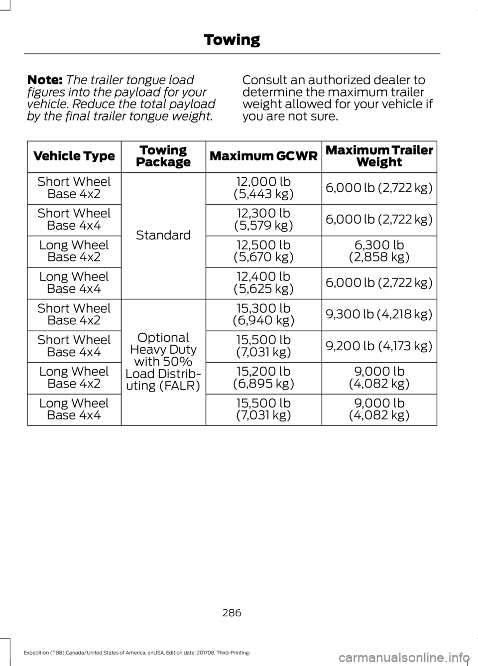
Your vehicle may tow a trailer
provided the maximum trailer
weight is less than or equal to the
maximum trailer weight listed for
your vehicle configuration on the
following chart.
To calculate the maximum loaded
trailer weight for your vehicle:
1. Start with the gross combined weight rating for your vehicle
model and axle ratio. See the
following chart.
2. Subtract all of the following
that apply to your vehicle:
•Vehicle curb weight.
• Hitch hardware weight, such
as a draw bar, ball, locks or
weight distributing.
• Driver weight.
• Passenger weight.
• Payload, cargo and luggage
weight.
• Aftermarket equipment
weight.
3. This equals the maximum
loaded trailer weight for this
combination.
285
Expedition (TB8) Canada/United States of America, enUSA, Edition date: 201708, Third-Printing- Towing
Page 289 of 571
Note:
The trailer tongue load
figures into the payload for your
vehicle. Reduce the total payload
by the final trailer tongue weight. Consult an authorized dealer to
determine the maximum trailer
weight allowed for your vehicle if
you are not sure. Maximum Trailer
Weight
Maximum GCWR
Towing
Package
Vehicle Type
6,000 lb (2,722 kg)
12,000 lb
(5,443 kg)
Standard
Short Wheel
Base 4x2
6,000 lb (2,722 kg)
12,300 lb
(5,579 kg)
Short Wheel
Base 4x4
6,300 lb
(2,858 kg)
12,500 lb
(5,670 kg)
Long Wheel
Base 4x2
6,000 lb (2,722 kg)
12,400 lb
(5,625 kg)
Long Wheel
Base 4x4
9,300 lb (4,218 kg)
15,300 lb
(6,940 kg)
Optional
Heavy Duty with 50%
Load Distrib- uting (FALR)
Short Wheel
Base 4x2
9,200 lb (4,173 kg)
15,500 lb
(7,031 kg)
Short Wheel
Base 4x4
9,000 lb
(4,082 kg)
15,200 lb
(6,895 kg)
Long Wheel
Base 4x2
9,000 lb
(4,082 kg)
15,500 lb
(7,031 kg)
Long Wheel
Base 4x4
286
Expedition (TB8) Canada/United States of America, enUSA, Edition date: 201708, Third-Printing- Towing