2018 FIAT DUCATO automatic operation
[x] Cancel search: automatic operationPage 10 of 304

SYMBOLS
Some vehicle components have
coloured labels whose symbols indicate
precautions to be observed when
using this component. Under the
bonnet there is also a label that
summarises all the symbols.
VEHICLE
MODIFICATIONS/
ALTERATIONS
IMPORTANT Any change or alteration
of the vehicle might seriously affect
its safety and road holding, thus
causing accidents, in which the
occupants could even be fatally injured.THE FIAT CODE
SYSTEM
IN BRIEF
This is an electrical engine locking
system which increases protection
against attempted theft of the vehicle.
It is automatically activated when
the key is removed from the ignition
device.
Each key contains an electronic
device which modulates the signal
emitted during ignition by an antenna
built into the ignition device. The
signal, which changes each time the
engine is started, is the “password”,
by means of which the control unit
recognises the key and enables
starting.
1)
Operation
Each time the vehicle is started turning
the ignition key toMAR-ON, the Fiat
CODE system control unit sends a
recognition code to the Powertrain
Control Module to deactivate the
immobiliser.The code is sent only if the Fiat CODE
system control unit has recognised
the code transmitted from the key.
Each time the ignition key is turned to
STOP, the Fiat CODE system
deactivates the functions of the engine
control module.
Irregular operation
If the code has not been recognised
correctly during starting, the
warning light on the instrument
panel turns on accompanied by the
corresponding message on the display
(see the “Warning lights and messages”
chapter).
In this case, turn the key toSTOPand
then back toMAR; if the lock
continues, try with the other keys
provided with the vehicle. Contact a
Fiat Dealership if you still cannot start
the engine.
IMPORTANT Each key has its own
code which must be stored by the
system's control unit. Contact a Fiat
Dealership to have new keys (up to 8)
stored with a code.
8
KNOWING YOUR VEHICLE
Page 15 of 304

Turn the metal insert anticlockwise fig. 6
in the driver's side door lock to unlock
all the doors. With the battery
disconnected, access to the vehicle will
only be possible by unlocking the
driver's door using the mechanical lock.
Locking/unlocking doors from the
inside
Press the button A fig. 7 to lock the
doors and press it again to unlock
them. Locking / unlocking is centralized
(front and rear).
When the doors are locked, the LED in
button A is on and, when the button
is pressed again, all the doors are
centrally unlocked and the warning light
is switched off.
When the doors are unlocked, the LED
is off and pressing the button again
centrally locks all the doors. The doors
will be locked only if all the doors are
properly shut.Following the locking of the doors
using:
remote control
door pawl
it will not be possible to unlock using
the button A fig. 7 on the dashboard.
IMPORTANT With the central locking
on, pulling the opening lever for one of
the front doors causes the central
locking to be switched off. Individual
doors can be unlocked by pulling
the opening handle of one of the rear
doors.
If a power supply is not present (blown
fuse, battery disconnected, etc.) it is,
however, possible to lock the doors
manually.
After exceeding 20 km/h, all the doors
will be locked automatically if the setup
menu function has been selected
(see “Multifunction display” paragraph
in this section).
LOCKING/UNLOCKING
THE LOAD
COMPARTMENT
The activation of the locking is signalled
by the LED in the button.
The LED comes on in the following
cases:
after each door lock command from
the D fig. 8 or
button on the
dashboard;
when the instrument panel is
activated;
upon opening of one of the front
doors;
when the door is locked at 20 km/h
(if activated from the menu).
The lock is turned off when one of the
load compartment doors is opened
or on a door release request (load
compartment or centralised) or
an unlocking request from the remote
control/door catch.
DEAD LOCK DEVICE
(for versions/markets, where provided)
It is a safety device that disables
operation of the interior handles.
Operate the lock/unlock button A fig. 7
to prevent opening the doors from
inside the passenger compartment in
the event of an attempted break-in (e.g.
when a window is broken).
7F1A0303
8F1A0116
13
Page 27 of 304
WARNING
27)Any steering wheel position adjustment
should only be carried out with the vehicle
stationary and the engine turned off.
28)It is absolutely forbidden to carry out
any after-market operation involving
steering system or steering column
modifications (e.g.: installation of anti-theft
device). This could badly affect
performance and safety, invalidate the
warranty and also result in the non-
compliance of the vehicle with approval
requirements.
REAR VIEW
MIRRORS
INTERIOR MIRROR
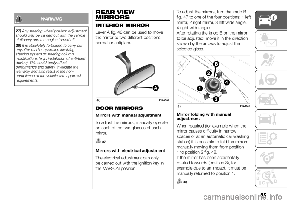
Lever A fig. 46 can be used to move
the mirror to two different positions:
normal or antiglare.
DOOR MIRRORS
Mirrors with manual adjustment
To adjust the mirrors, manually operate
on each of the two glasses of each
mirror.
29)
Mirrors with electrical adjustment
The electrical adjustment can only
be carried out with the ignition key in
the MAR-ON position.To adjust the mirrors, turn the knob B
fig. 47 to one of the four positions: 1 left
mirror, 2 right mirror, 3 left wide angle,
4 right wide angle.
After rotating the knob B on the mirror
to be adjusted, move it in the direction
shown by the arrows to adjust the
selected glass.
Mirror folding with manual
adjustment
When required (for example when the
mirror causes difficulty in narrow
spaces or at an automatic car washing
station) it is possible to fold the mirrors
manually moving them from position
1 to position 2 fig. 48.
If the mirror has been accidentally
rotated forwards (position 3), for
example due to an impact, it must be
manually returned to position 1.
30)
46F1A0353
47F1A0042
25
Page 29 of 304

WARNING
29)As the driver's exterior mirror is curved,
it may slightly alter the perception of
distance of the reflected image. Further,
the reflective surface of the lower part
of the exterior mirrors is parabolic to
increase the field of view. The reflected
image size is thus reduced and gives the
impression that the reflected item is further
away than it actually is.
30)When driving the mirrors should always
remain in position 1.
EXTERIOR LIGHTS
IN BRIEF
The left stalk includes the controls for
the exterior lights.
Theexterior lights can only be
switched on when the ignition key is
in the ON position.
LIGHTS OFF
Ring turned to theOfig. 50 position.DAYTIME RUNNING
LIGHTS (DRL)
(for versions/markets, where provided)
With the key in MAR position and
the ring turned to theOposition fig. 50,
the daytime lights turn on automatically;
the other lights and the internal lighting
remain off. The automatic operation
of the daytime running lights can be
activated/deactivated, for versions/
markets where provided, via the display
menu (see "Display" in the "Knowing
the instrument panel" chapter).
If the daytime running lights are
deactivated, no light comes on when
the ring nut is turned toO.
31)
DIPPED HEADLIGHTS/
SIDE LIGHTS
With the ignition key turned to
MAR-ON, turn the ring nut to
fig.
51.
If dipped headlights are activated, the
daytime running lights switch off and
the side lights and dipped headlights
switch on.
The
warning light switches on in
the instrument panel.
When the ignition key is turned to
STOP or removed and the ring nut is
turned fromOto
, all the side lights
and the number plate lights come on.
50F1A0064
27
Page 33 of 304

FOG LIGHTS ALIGNMENT
(for versions/markets, where provided)
Contact a Fiat Dealership to have the
headlights checked and adjusted.
ADJUSTING THE
HEADLIGHTS WHEN
ABROAD
The dipped beam headlights are
aligned for operation in the country
where the vehicle was originally
purchased. When in countries where
you drive on the other side of the road,
you need to alter the light beam
direction by affixing a specially designed
self-adhesive film in order not to dazzle
the vehicles travelling in the opposite
direction. This film is provided by
Lineaccessori MOPAR and is available
at Fiat Dealerships.
CEILING LIGHTS
FRONT ROOF LIGHT WITH
SPOT LIGHTS
The switch A fig. 58 is used to switch
the roof lights on/off. With the switch A
in the middle position, the lights C
and D go on/off when front doors are
opened/closed. With switch A pressed
to the left, the lights C and D are always
off. With switch A pressed to the right,
the lights C and D are always on.
Lights switch on/off progressively.
The switch B is a spot light; when the
roof light is off, it switches the following
on individually:
light C if pressed on the left side;
light D if pressed on the right side.
The timed period ends automatically
when the doors are locked.Ceiling light timing
On some versions, to facilitate getting
in/out of the vehicle at night or with
poor lighting, 2 different timed modes
are available.
for entering the vehicle;
for leaving the vehicle;
REMOVABLE CEILING
LIGHT
(for versions/markets, where provided)
It is used as both a fixed light and a
portable electric torch.
When the removable light is connected
to its fixed mount fig. 59, the electric
torch battery is automatically
recharged.
With the vehicle stationary and the
ignition key either turned to STOP or
removed, the roof light is recharged for
a maximum of 15 minutes.
MODEMODE
57F1A0326
58F1A0074
59F1A0077
31
Page 37 of 304

Temporary fast operation in position E
is limited to the time that the lever is
manually held in this position. The lever
returns to position A when it is
released, automatically stopping the
windscreen wipers.
4)
IMPORTANT We recommend replacing
the blades once a year.“Smart washing” function
Pulling the stalk towards the steering
wheel (unstable position) operates
the windscreen washer fig. 70.
Keeping the stalk pulled for more than
half a second, with just one movement
it is possible to operate the washer
jet and the wiper at the same time.
The windscreen wiper stops working
three strokes after the stalk is released.
A further stroke after approx. 6 seconds
completes the wiping cycle.
RAIN SENSOR
(for versions/markets, where provided)
The rain sensor is located behind the
driving mirror in contact with the
windscreen and has the purpose of
automatically adjust, during the
intermittent operation, the frequency of
the windscreen wiper strokes as to
the rain intensity.IMPORTANT Keep the glass in the
sensor area clean.
Activation fig. 69
Move the right lever down by one click
(position B).
The activation of the sensor is signalled
by a "stroke" to show that the
command has been acquired.
Turn the control F to increase the rain
sensor sensitivity.
The increasing of the rain sensor
sensitivity is signalled by a "stroke" to
show that the command has been
acquired.
If the windscreen washer is used with
the rain sensor activated, the normal
washing cycle is performed, after which
the rain sensor resumes its normal
automatic operation.
Deactivation fig. 69
Move the lever from position B or turn
the ignition key to OFF. The next time
the vehicle is started (ignition key in ON
position), the sensor is not reactivated
even if the lever is still in position B.
To activate the sensor, move the lever
to position A or C and then back to
position B or turn the ring nut for
adjusting the sensitivity. Rain sensor
activation will be indicated by at least
one wiper “stroke” even if the
windscreen is dry.
69F1A0071
70F1A0072
35
Page 38 of 304

The rain sensor is capable of
recognising the difference between day
and night and making the necessary
adjustments automatically.
34)
HEADLIGHT WASHERS
(for versions/markets, where provided)
The headlight washers are “retractable”,
i.e.: they are located inside the front
bumper and they are activated when
(with dipped beams on) the windscreen
washer is operated.
IMPORTANT Check the correct
condition and cleanliness of nozzles at
regular intervals.
WARNING
34)Streaks of water may cause
unnecessary blade movements.
WARNING
4)Never use the windscreen wiper to
remove layers of snow or ice from
the windscreen. In such conditions, the
windscreen wiper may be subjected to
excessive stress and the motor cut-out
switch, which prevents operation for a few
seconds, may intervene. If operation is
not restored, contact a Fiat Dealership.
36
KNOWING YOUR VEHICLE
Page 41 of 304

Air distribution ring nut C
to convey air to the central and
side vents;
to warm the feet and convey
slightly cooler air to the dashboard
vents, in intermediate temperature
conditions;
for heating when the outside
temperature is very low: to direct
as much air as possible to the
feet;
to warm the feet and demist the
windscreen at the same time;
for quick windscreen demisting.
Air recirculation on/off knob D
Press the button (button LED on) to
turn the internal air recirculation on.
Press the button again (button LED off)
to turn the internal air recirculation off.
Climate control system on/off
button E
Press the button (button LED on) to
turn the climate control system on.
Press the button again (button LED off)
to turn the climate control system off.
AUTOMATIC
CLIMATE CONTROL
SYSTEM
2)
(for versions/markets, where provided)
CONTROLS
AAUTO button automatic control of all
functions.
BAir distribution selection button.
CDisplay.
DMAX DEF function control button.
ESystem off button.
FCompressor enabling/disabling
control button.
GAir recirculation control button.
HFan speed increase/decrease control
buttons.
ITemperature increase/decrease
control knob.USING THE CLIMATE
CONTROL SYSTEM
The system can be started in different
ways, but it is advisable to start by
pressing the AUTO button and then
turning the knob to set the temperature
required on the display.
The system will adjust the temperature,
the quantity and the distribution of the
air sent into the passenger
compartment and, by managing the
recirculation function, the activation of
the climate control system compressor.
During fully automatic operation, the
only manual intervention required is the
possible activation of the following
functions:
air recirculation (to keep the
recirculation constantly on or constantly
off);
to speed up demisting/
defrosting the windscreen, rearscreen
and external rear-view mirrors.
74F1A0054
39