2018 FIAT 124 SPIDER Owner handbook (in English)
-
 1
1 -
 2
2 -
 3
3 -
 4
4 -
 5
5 -
 6
6 -
 7
7 -
 8
8 -
 9
9 -
 10
10 -
 11
11 -
 12
12 -
 13
13 -
 14
14 -
 15
15 -
 16
16 -
 17
17 -
 18
18 -
 19
19 -
 20
20 -
 21
21 -
 22
22 -
 23
23 -
 24
24 -
 25
25 -
 26
26 -
 27
27 -
 28
28 -
 29
29 -
 30
30 -
 31
31 -
 32
32 -
 33
33 -
 34
34 -
 35
35 -
 36
36 -
 37
37 -
 38
38 -
 39
39 -
 40
40 -
 41
41 -
 42
42 -
 43
43 -
 44
44 -
 45
45 -
 46
46 -
 47
47 -
 48
48 -
 49
49 -
 50
50 -
 51
51 -
 52
52 -
 53
53 -
 54
54 -
 55
55 -
 56
56 -
 57
57 -
 58
58 -
 59
59 -
 60
60 -
 61
61 -
 62
62 -
 63
63 -
 64
64 -
 65
65 -
 66
66 -
 67
67 -
 68
68 -
 69
69 -
 70
70 -
 71
71 -
 72
72 -
 73
73 -
 74
74 -
 75
75 -
 76
76 -
 77
77 -
 78
78 -
 79
79 -
 80
80 -
 81
81 -
 82
82 -
 83
83 -
 84
84 -
 85
85 -
 86
86 -
 87
87 -
 88
88 -
 89
89 -
 90
90 -
 91
91 -
 92
92 -
 93
93 -
 94
94 -
 95
95 -
 96
96 -
 97
97 -
 98
98 -
 99
99 -
 100
100 -
 101
101 -
 102
102 -
 103
103 -
 104
104 -
 105
105 -
 106
106 -
 107
107 -
 108
108 -
 109
109 -
 110
110 -
 111
111 -
 112
112 -
 113
113 -
 114
114 -
 115
115 -
 116
116 -
 117
117 -
 118
118 -
 119
119 -
 120
120 -
 121
121 -
 122
122 -
 123
123 -
 124
124 -
 125
125 -
 126
126 -
 127
127 -
 128
128 -
 129
129 -
 130
130 -
 131
131 -
 132
132 -
 133
133 -
 134
134 -
 135
135 -
 136
136 -
 137
137 -
 138
138 -
 139
139 -
 140
140 -
 141
141 -
 142
142 -
 143
143 -
 144
144 -
 145
145 -
 146
146 -
 147
147 -
 148
148 -
 149
149 -
 150
150 -
 151
151 -
 152
152 -
 153
153 -
 154
154 -
 155
155 -
 156
156 -
 157
157 -
 158
158 -
 159
159 -
 160
160 -
 161
161 -
 162
162 -
 163
163 -
 164
164 -
 165
165 -
 166
166 -
 167
167 -
 168
168 -
 169
169 -
 170
170 -
 171
171 -
 172
172 -
 173
173 -
 174
174 -
 175
175 -
 176
176 -
 177
177 -
 178
178 -
 179
179 -
 180
180 -
 181
181 -
 182
182 -
 183
183 -
 184
184 -
 185
185 -
 186
186 -
 187
187 -
 188
188 -
 189
189 -
 190
190 -
 191
191 -
 192
192 -
 193
193 -
 194
194 -
 195
195 -
 196
196 -
 197
197 -
 198
198 -
 199
199 -
 200
200 -
 201
201 -
 202
202 -
 203
203 -
 204
204 -
 205
205 -
 206
206 -
 207
207 -
 208
208 -
 209
209 -
 210
210 -
 211
211 -
 212
212 -
 213
213 -
 214
214 -
 215
215 -
 216
216 -
 217
217 -
 218
218 -
 219
219
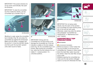
 IMPORTANT
12)Never open the soft top in presence of
snow or ice to prevent damage.
13)Loads may not be secured on the roof.
14)Bird droppings and plant resins must
be washed off the soft top immediate")
 KNOWING THE INSTRUMENT PANEL
This section of the owner handbook
gives you all the information you need
to understand, interpret and use the
instrument panel correctly.CONTROL PANEL AND
INSTRUMENTS....")
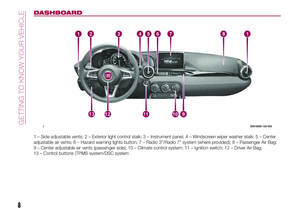
 CONTROL PANEL AND INSTRUMENTS
1. Odometer/Trip meter and Trip computer button/Dashboard illumination - 2. Tachometer - 3. Speedometer - 4. Automatic
transmission info display - 5. Odometer/Trip comput")
 RIGHT-HAND DRIVE VERSIONS
1. Odometer/Trip meter and Trip computer button/Dashboard illumination - 2. Tachometer - 3. Speedometer - 4. Automatic
transmission info display - 5. Odometer/Trip computer i")
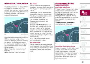
 ODOMETER / TRIP METER
The display mode can be changed from
odometer to “Trip meter A” to “Trip
meter B” and then back to odometer by
pressing the selector 1 fig. 52 while one
of them is displa")
 When the illumination dimmer is
canceled, the instrument cluster cannot
be dimmed even if the position lights
are turned on. When the illumination
dimmer is canceled, the screen in the
center display")
 press the INFO switch and set the
two lower digits (tenths and ones place)
to the desired vehicle speed. The
numerical value changes each time the
INFO switch is pressed;
press the INFO switch continu")
 54
KNOWING THE INSTRUMENT PANEL
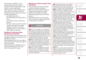
IMPORTANT The indication of the
warning light in the instrument panel
is indicative and precautionary
and as such must not be
considered as exhaustive and/or
alternati")