Page 121 of 220
 warning light (green) turns on.
The cruise control speed setting cannot
be performed under the following
conditions:
Automatic transmission: the
selector lever is in the P or N position;
Manual transm")
warning light (green) turns on.
The cruise control speed setting cannot
be performed under the following
conditions:
Automatic transmission: the
selector lever is in the P or N position;
Manual transmission: the shift
lever is in the neutral position;
The parking brake is applied;
Vehicles with Speed limiter: the
MODE switch for the adjustable speed
limiter is pressed.
Release the SET/- switch at the
desired speed, otherwise the speed will
continue decreasing while the SET/-
switch is pressed and held (except
when the accelerator pedal is
depressed);
On a steep grade, the vehicle may
momentarily slow down while
ascending, or speed up while
descending.
The cruise control will cancel if the
vehicle speed decreases below
21 km/h when climbing a steep grade.
The cruise control may cancel at
about 15 km/h below the preset speed
such as when climbing a long, steep
grade.
The vehicle speed preset using the
cruise control is displayed in the
instrument cluster.
INCREASING /
DECREASING SPEED
To increase speed
With cruise control switch: press the
RESUME/+ switch and hold it your
vehicle will accelerate. Release the
switch at the desired speed. Press the
RESUME/+ switch and release it
immediately to adjust the preset speed.
Multiple operations will increase the
preset speed according to the number
of times it is operated.
Using accelerator pedal: depress the
accelerator pedal to accelerate to the
desired speed. Press the SET/- switch
and release it immediately.
IMPORTANT Accelerate if you want to
speed up temporarily when the cruise
control is on. Greater speed will not
interfere with or change the set speed.
Take your foot off the accelerator to
return to the set speed.
RESUME SPEED
If some other method besides the
OFF/CANCEL switch was used to
cancel cruising speed (such as applying
the brake pedal) and the system is still
activated, the most recent set speed
will automatically resume when the
RESUME/+ switch is pressed.
If vehicle speed is below 25 km/h,
increase the vehicle speed up to25 km/h or more and press the
RESUME/+ switch.
TEMPORARILY
CANCELLING THE
SYSTEM
To temporarily cancel the system, use
one of these methods: slightly depress
the brake pedal/depress the clutch
pedal (versions with manual
transmission)/press the OFF/CANCEL
switch.
If the RESUME/+ switch is pressed
when the vehicle speed is 25 km/h or
higher, the system reverts to the
previously set speed.
Note
If any of the following conditions occur,
the cruise control system is temporarily
canceled:
the parking brake is applied;
Versions with Speed limiter: the
MODE switch for the adjustable speed
limiter is pressed;
Automatic transmission: the
selector lever is in the P or N position or
on versions withmanual
transmission: the shift lever is in the
neutral position;
Automatic transmission: the cruise
control cannot be cancelled while
driving in manual mode (selector lever
shifted from D to M position). Therefore,
engine braking will not be applied even
119
Page 122 of 220
 if the transaxle is shifted down to a
lower gear. If deceleration is required,
lower the set speed or depress the
brake pedal;
When the cruise control system is
temporarily canceled by even one of the")
if the transaxle is shifted down to a
lower gear. If deceleration is required,
lower the set speed or depress the
brake pedal;
When the cruise control system is
temporarily canceled by even one of the
applicable cancel conditions, the speed
cannot be reset.
WARNING
144)Always turn off the cruise control
system when it is not in use: leaving the
cruise control system in an activation-ready
state while the cruise control is not in use is
dangerous as the cruise control could
unexpectedly activate if the activation
button is accidentally pressed, and result in
loss of vehicle control and an accident.
145)While travelling with the device
activated, do not move the gear lever to
neutral.
146)In the event of device faults or failures,
go to a Fiat Dealership.
147)The cruise control can be dangerous
if the system cannot keep a constant
speed. In specific conditions speed may be
excessive, resulting in the risk of losing
control of the vehicle and causing
accidents. Do not use the device in heavy
traffic or on winding, icy, snowy or slippery
roads.
SPEED LIMITER
(where provided)
148) 149)
The speed limiter can be set between
30 km/h and 200 km/h.
The system consists of the speed
limiter display and the switch on the
steering wheel fig. 92.
ACTIVATION /
DEACTIVATION
Activation
Press the ON switch to operate the
system. The adjustable speed limiter
screen is displayed, and the speed
limiter main indicator light (amber) turns
on.
IMPORTANT When the cruise control is
operating after pressing the ON switch,
press the mode switch again to switch
to the adjustable speed limiter.
Deactivation
To deactivate the system, do the
following operations:
When a cruising speed has been
set(warning light green turns on):
long-press the OFF/CAN switch or
press the OFF/CAN switch 2 times. The
speed limiter screen is no longer
displayed and the speed limiter set
indicator light (green) turns off.
When a cruising speed has not
been set(warning light amber turns
on): press the OFF/CAN switch. The
speed limiter screen is no longer
displayed and the adjustable speed
limiter set indicator light (amber) turns
off.
When the ON switch is pressed during
adjustable speed limiter operation, the
system switches to the cruise control.
9205281500-12A-002
120
STARTING AND OPERATING
Page 123 of 220
 SETTING A DESIRED
SPEED
Proceed as follows:
press the ON switch to turn the
system on;
press the SET/- to set the speed.
When the current vehicle speed is
30 km/h or more, the speed is set to
the curr")
SETTING A DESIRED
SPEED
Proceed as follows:
press the ON switch to turn the
system on;
press the SET/- to set the speed.
When the current vehicle speed is
30 km/h or more, the speed is set to
the current vehicle speed. When the
current vehicle speed is less than
30 km/h, the speed is set to 30 km/h;
to increase the set speed: press
the RES/+ switch continuously.To
decrease the set speed: press the
SET/- switch continuously.
NOTE When the vehicle set speed is
displayed in the instrument cluster,
press the RES/+ switch to set the
displayed vehicle speed.
NOTE The vehicle speed may exceed
the set speed on a down slope.
TEMPORARILY
CANCELLING THE
SYSTEM
The system is temporarily cancelled
(stand-by status) when any of the
following operations is done while the
speed limiter is displayed:
OFF/CAN switch is pressed;
accelerator pedal is strongly
depressed.
Press the RES/+ switch to resume the
operation at the previous set speed.The set speed can be set by pressing
the SET/- switch while the system is in
stand-by status.
WARNING
148)Always turn off the system when
changing drivers. If the driver is changed
and the new driver is unaware of the speed
limiter function, the vehicle may not
accelerate when the driver depresses the
accelerator pedal, leading to an accident.
149)Always verify the safety of the
surrounding area and keep a safer distance
between vehicles ahead and behind you
when setting the speed limiter. If the speed
is set lower than the current vehicle speed,
the vehicle speed is decreased to the set
speed.
PARKING SENSOR
SYSTEM
(where provided)
150) 151)
26) 27) 28)
The parking sensor system uses
4 ultrasonic sensors (2 rear sensors and
2 rear corner sensors) fig. 93 to detect
obstructions around the vehicle while
parking the vehicle in a garage or
during parallel parking when the shift
lever (manual transmission)/selector
lever (automatic transmission) is in
reverse (R).
9305200100-121-001
121
Page 124 of 220
 SENSOR DETECTION
RANGE
The sensors detect obstructions within
the following range:
Lateral detection range: about
50 cm
Rear detection range: about
150 cm
SYSTEM OPERATION
When the ignition is switche")
SENSOR DETECTION
RANGE
The sensors detect obstructions within
the following range:
Lateral detection range: about
50 cm
Rear detection range: about
150 cm
SYSTEM OPERATION
When the ignition is switched ON and
the shift lever (manual transmission)/
selector lever (automatic transmission)
is shifted to the reverse (R), the beep
sound activates and the system is
enabled for use.
WARNING
150)Do not rely completely on the parking
sensor system and be sure to confirm the
safety around your vehicle visually when
driving. This system can assist the driver in
operating the vehicle in the forward and
backward directions while parking. The
detection ranges of the sensors are limited,
therefore, driving the vehicle while relying
only on the system may cause an accident.
Always confirm the safety around your
vehicle visually when driving.
151)Parking and other potentially
dangerous manoeuvres are, however,
always the driver’s responsibility. When
performing these operations, always make
sure that there are no other people
(especially children) or animals on the route
you want to drive into. The parking sensors
are an aid for the driver, but the driver must
never allow their attention to lapse during
potentially dangerous manoeuvres, even
those executed at low speeds.
IMPORTANT
26)Only have interventions on the bumper
in the area of the sensors carried out by a
Fiat Dealership. Interventions on the
bumper that are not carried out properly
may compromise the operation of the
parking sensors.
27)Only have the bumpers repainted or
any retouches to the paintwork in the area
of the sensors carried out by a Fiat
Dealership. Incorrect paint application
could affect the operation of the parking
sensors.
28)The sensors must be clean of mud,
dirt, snow or ice in order for the system to
operate correctly. Be careful not to scratch
or damage the sensors while cleaning
them. Avoid using dry, rough or hard
cloths. The sensors should be washed
using clean water with the addition of car
shampoo if necessary. When using special
washing equipment such as high pressure
jets or steam cleaning, clean the sensors
very quickly keeping the jet more than
10 cm away.
122
STARTING AND OPERATING
Page 125 of 220
 REFUELLING THE
VEHICLE
152) 153) 154) 155) 156) 157)
Always stop the engine before
refuelling.
FUEL REQUIREMENTS
Only use premium unleaded fuel
(conforming to EN 228 specification
within E10) with a n")
REFUELLING THE
VEHICLE
152) 153) 154) 155) 156) 157)
Always stop the engine before
refuelling.
FUEL REQUIREMENTS
Only use premium unleaded fuel
(conforming to EN 228 specification
within E10) with a number of octanes
not lower than 95.
IMPORTANT USE ONLY UNLEADED
FUEL. Leaded fuel is harmful to the
catalytic converter and oxygen sensors
and will lead to deterioration of the
emission control system and or failures.
IMPORTANT The use of E10 fuel with
10% ethanol in Europe is safe for your
vehicle. Damage to your vehicle may
occur when ethanol exceeds this
recommendation.
IMPORTANT Never add fuel system
additives, otherwise the emission
control system could be damaged.
Contact a Fiat Dealership for details.
REFUELLING
PROCEDURE
When the fuel filler flap end is pressed
with the doors unlocked, the fuel filler
flap rises fig. 94.The fuel filler flap operates in
conjunction
with the doorlocking/unlocking mechanism.
To close, press the fuel filler flap until a
click sound is heard.
IMPORTANT Make sure to lock both
the doors when leaving the vehicle.
IMPORTANT Lock the doors after
closing the fuel flap. If the fuel flap is
closed after locking the doors, the fuel
flap cannot be locked.
Fuel filler cap
To remove the fuel filler cap, turn it
anticlockwise fig. 95. Attach the
removed cap to the inner side of the
fuel flap.
To close the fuel filler cap, turn it
clockwise until a click is heard.
EMERGENCY FLAP
OPENING
In case of emergency (e.g. when the
battery is dead), to open the fuel filler
flap proceed as follows:
open the boot lid and pull the center
section of the plastic fastener 1 and
remove the fastener fig. 96;
partially peel back the cover 2
fig. 96 inside the boot, then pull the
emergency release lever 3 fig. 97.
9404040201-12A-0029504040202-12A-001-high.jpg
123
9608100100-121-002
Page 126 of 220
 WARNING
152)When removing the fuel filler cap,
loosen the cap slightly and wait for any
hissing to stop, then remove it: fuel spray is
dangerous. Fuel can burn skin and eyes
and cause illness if inges")
WARNING
152)When removing the fuel filler cap,
loosen the cap slightly and wait for any
hissing to stop, then remove it: fuel spray is
dangerous. Fuel can burn skin and eyes
and cause illness if ingested. Fuel spray is
released when there is pressure in the fuel
tank and the fuel filler cap is removed too
quickly.
153)Before refuelling, stop the engine, and
always keep sparks and flames away from
the filler neck: fuel vapour is dangerous. It
could be ignited by sparks or flames
causing serious burns and injuries.
Additionally, use of the incorrect fuel filler
cap or not using a fuel filler cap may result
in a fuel leak, which could result in serious
burns or death in an accident.
154)Do not continue refuelling after the
fuel pump nozzle shuts off automatically:
continuing to add fuel after the fuel pump
nozzle has shut off automatically is
dangerous because overfilling the fuel tank
may cause fuel overflow or leakage. Fuel
overflow and leakage could damage the
vehicle and if the fuel ignites it could cause
a fire and explosion resulting in serious
injury or death.
155)Do not apply any object/plug to the
end of the filler which is not provided for
the car. The use of non-compliant
objects/plugs could cause a pressure
increase inside the tank, resulting in
dangerous situations.
156)Do not bring naked flames or lit
cigarettes near to the fuel filler: fire risk.
Keep your face away from the fuel filler to
prevent breathing in harmful vapours.
157)Do not use a mobile phone near the
refuelling pump: risk of fire.
9708100100-122-001
124
STARTING AND OPERATING
Fuels - identification of
vehicle compatibility
Symbol for consumer
information in accordance
with theEN16942
specification
The symbols shown below help you to
recognise the correct type of fuel to use
in your vehicle. Before proceeding with
refuelling, check the symbols inside the
fuel filler flap (where provided) and
compare
them
with
the
symbols
shown
on the fuel pump (where provided).
E5: Unleaded petrol containing up to
2,7% (m/m) oxygen and with maximum
5,0% (V/V) ethanol compliant with the
EN228
E10: Unleaded petrol containing up to
3,7% (m/m) oxygen and with maximum
10,0% (V/V) ethanol compliant with the
EN228
specification
specification
Page 127 of 220
 IMPORTANT When parking, take the
utmost care over obstacles that may be
above or under the camera range.
IMPORTANT Always use extreme
caution and verify the real conditions of
the area behind the vehi")
IMPORTANT When parking, take the
utmost care over obstacles that may be
above or under the camera range.
IMPORTANT Always use extreme
caution and verify the real conditions of
the area behind the vehicle with you
own eyes. Reversing while looking only
at the screen is dangerous and can
lead to an accident or collision with an
object. The rear-view monitor is simply
a system to aid reversing. The images
on the screen can show a situation that
differs from the real one.
When the display is cold, the images
could scroll on the monitor or the
screen and could be more blurred than
usual, making it difficult to check the
conditions of the area around the
vehicle. Always use extreme caution
and verify the real conditions of the area
behind the vehicle with you own eyes.
IMPORTANT Do not apply excessive
force to the camera. You could alter the
position and angle of the camera. Do
not disassemble, modify or remove it as
this could compromise the hermetic
seal.
IMPORTANT The camera cover is
made of plastic. Do not apply
degreasing agents, organic solvents,
wax, or glass coating agents to thecamera cover. If any are spilled on the
cover, wipe off with a soft cloth
immediately.
IMPORTANT Do not rub the camera
cover forcefully with an abrasive or hard
brush. The camera cover or lens may
be scratched which might affect the
images.
IMPORTANT If water, snow or mud is
deposited on the camera lens, clean it
with a soft cloth. If this does not clean
it, use a mild detergent.
IMPORTANT If the camera is subjected
to abrupt temperature changes (from
hot to cold or vice versa), the rear-view
monitor may not work properly.
IMPORTANT When replacing tires,
contact a Fiat Dealership. Replacing the
tires can cause the guide lines that
appear on the display to be diverted.
IMPORTANT If the vehicle has been
involved in a frontal, lateral or rear
collision, the rear parking camera’s
alignment (location or installation angle)
may have been altered. Contact a Fiat
Dealership.
IMPORTANT If the display shows "no
video signal", there may be a problem
with the camera. Contact a Fiat
Dealership.
125
REAR CAMERA
(PARKVIEW REAR
BACKUP CAMERA)
(only versions with Radio 7” system)
OPERATION
158)
29)
The camera is located on the tailgate
fig. 98.
Switching to the rear view monitor
display
Shift the selector lever or shift lever to
reverse (R) with the ignition switched
ON to switch the display to the rear
view monitor display.
9807040110-124-008
Page 128 of 220
 IMPORTANT The guide lines are fixed
on the screen. They are not
synchronized with the driver’s actions
on the steering wheel. Always use the
utmost caution and check the area
behind the vehicle and")
IMPORTANT The guide lines are fixed
on the screen. They are not
synchronized with the driver’s actions
on the steering wheel. Always use the
utmost caution and check the area
behind the vehicle and the surrounding
area with your own eyes when
reversing.
REAR VIEW MONITOR
OPERATION
NOTE Images displayed on the monitor
from the rear view parking camera are
reversed images (mirror images).
Give due consideration to the above
warnings before you use the rear-view
monitor:
shift the selector lever or shift lever to
reverse (R) to switch the display to the
rear view monitor display A fig. 100;
confirming the surrounding
conditions, reverse the vehicle B
fig. 100;
after your vehicle begins entering the
parking space, continue backing up
slowly so that the distance between the
vehicle width lines and the sides of the
parking space on the left and right are
roughly equal;
continue to adjust the steering wheel
until the vehicle width guide lines are
parallel to the left and right sides of the
parking space;
once they are parallel Afig. 101,
straighten the wheels and back your
vehicle slowly into the parking space B
10007080913-989-989
126
STARTING AND OPERATING
VIEWING THE DISPLAY
Guide lines which indicate the width of
the vehicle (yellow)fig. 99 are displayed
on the screen as a reference to the
approximate width of the vehicle in
comparison to the width of the parking
space you are about to back into.
Use this display view for parking your
vehicle in a parking space or garage.
vehicle width guide lines (yellow):
these guide lines serve as a reference
showing the width of the vehicle.
distance guide lines: these lines
indicate the approximate distance of a
point measured from the rear of the
vehicle (from the end of the bumper).
The red and yellow line indicates the
points at about 50 cm, for the red line
and 1 m for the yellow line, from the
rear bumper (central point of each line).
9907080913-111-111
 1
1 2
2 3
3 4
4 5
5 6
6 7
7 8
8 9
9 10
10 11
11 12
12 13
13 14
14 15
15 16
16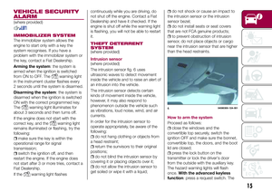 17
17 18
18 19
19 20
20 21
21 22
22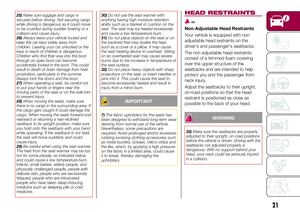 23
23 24
24 25
25 26
26 27
27 28
28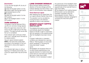 29
29 30
30 31
31 32
32 33
33 34
34 35
35 36
36 37
37 38
38 39
39 40
40 41
41 42
42 43
43 44
44 45
45 46
46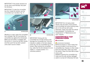 47
47 48
48 49
49 50
50 51
51 52
52 53
53 54
54 55
55 56
56 57
57 58
58 59
59 60
60 61
61 62
62 63
63 64
64 65
65 66
66 67
67 68
68 69
69 70
70 71
71 72
72 73
73 74
74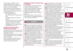 75
75 76
76 77
77 78
78 79
79 80
80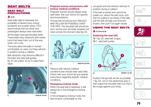 81
81 82
82 83
83 84
84 85
85 86
86 87
87 88
88 89
89 90
90 91
91 92
92 93
93 94
94 95
95 96
96 97
97 98
98 99
99 100
100 101
101 102
102 103
103 104
104 105
105 106
106 107
107 108
108 109
109 110
110 111
111 112
112 113
113 114
114 115
115 116
116 117
117 118
118 119
119 120
120 121
121 122
122 123
123 124
124 125
125 126
126 127
127 128
128 129
129 130
130 131
131 132
132 133
133 134
134 135
135 136
136 137
137 138
138 139
139 140
140 141
141 142
142 143
143 144
144 145
145 146
146 147
147 148
148 149
149 150
150 151
151 152
152 153
153 154
154 155
155 156
156 157
157 158
158 159
159 160
160 161
161 162
162 163
163 164
164 165
165 166
166 167
167 168
168 169
169 170
170 171
171 172
172 173
173 174
174 175
175 176
176 177
177 178
178 179
179 180
180 181
181 182
182 183
183 184
184 185
185 186
186 187
187 188
188 189
189 190
190 191
191 192
192 193
193 194
194 195
195 196
196 197
197 198
198 199
199 200
200 201
201 202
202 203
203 204
204 205
205 206
206 207
207 208
208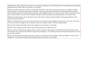 209
209 210
210 211
211 212
212 213
213 214
214 215
215 216
216 217
217 218
218 219
219