Page 109 of 696

IconDescription
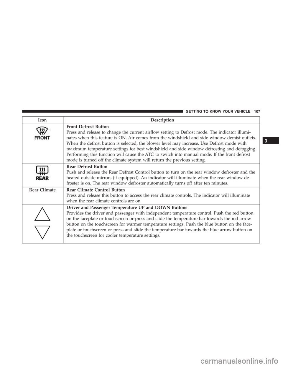
Front Defrost Button
Press and release to change the current airflow setting to Defrost mode. The indicator illumi-
nates when this feature is ON. Air comes from the windshield and side window demist outlets.
When the defrost button is selected, the blower level may increase. Use Defrost mode with
maximum temperature settings for best windshield and side window defrosting and defogging.
Performing this function will cause the ATC to switch into manual mode. If the front defrost
mode is turned off the climate system will return the previous setting.
Rear Defrost Button
Push and release the Rear Defrost Control button to turn on the rear window defroster and the
heated outside mirrors (if equipped). An indicator will illuminate when the rear window de-
froster is on. The rear window defroster automatically turns off after ten minutes.
Rear Climate Rear Climate Control Button Press and release this button to access the rear climate controls. The indicator will illuminate
when the rear climate controls are on.
Driver and Passenger Temperature UP and DOWN Buttons
Provides the driver and passenger with independent temperature control. Push the red button
on the faceplate or touchscreen or press and slide the temperature bar towards the red arrow
button on the touchscreen for warmer temperature settings. Push the blue button on the face-
plate or touchscreen or press and slide the temperature bar towards the blue arrow button on
the touchscreen for cooler temperature settings.
3
GETTING TO KNOW YOUR VEHICLE 107
Page 122 of 696

IconDescription
Front Defrost Button
Press and release to change the current airflow setting to Defrost mode. The indicator illumi-
nates when this feature is ON. Air comes from the windshield and side window demist outlets.
When the defrost button is selected, the blower level may increase. Use Defrost mode with
maximum temperature settings for best windshield and side window defrosting and defogging.
Performing this function will cause the ATC to switch into manual mode. If the front defrost
mode is turned off the climate system will return the previous setting.
Rear Defrost Button
Push and release the Rear Defrost Control button to turn ON the rear window defroster and the
heated outside mirrors (if equipped). An indicator will illuminate when the rear window de-
froster is ON. The rear window defroster automatically turns OFF after ten minutes.
Rear Climate Rear Climate Control Button Press and release this button to access the rear climate controls. The indicator will illuminate
when the rear climate controls are ON.
Driver And Passenger Temperature UP And DOWN Buttons
Provides the driver and passenger with independent temperature control. Push the red button
on the faceplate or touchscreen or press and slide the temperature bar towards the red arrow
button on the touchscreen for warmer temperature settings. Push the blue button on the face-
plate or touchscreen or press and slide the temperature bar towards the blue arrow button on
the touchscreen for cooler temperature settings.
120 GETTING TO KNOW YOUR VEHICLE
Page 183 of 696

GETTING TO KNOW YOUR INSTRUMENT PANEL
CONTENTS
�INSTRUMENT CLUSTER ..................182
▫ Instrument Cluster Descriptions ............183
� INSTRUMENT CLUSTER DISPLAY ...........185
▫ Instrument Cluster Display Location And
Controls ............................ .185
▫ Oil Life Reset ........................ .187
▫ KeySense Cluster Messages — If Equipped .....188
▫ Instrument Cluster Display Menu Items ......189
▫ Battery Saver On/Battery Saver Mode
Message — Electrical Load Reduction
Actions — If Equipped ..................195
� TRIP COMPUTER .......................197 �
WARNING LIGHTS AND MESSAGES .........197
▫ Red Warning Lights .....................198
▫ Yellow Warning Lights ...................202
▫ Yellow Indicator Lights ...................206
▫ Green Indicator Lights ...................206
▫ Blue Indicator Lights ....................208
▫ White Indicator Lights ...................208
� ONBOARD DIAGNOSTIC SYSTEM — OBD II . . .209
▫ Onboard Diagnostic System (OBD II)
Cybersecurity ........................ .209
� EMISSIONS INSPECTION AND MAINTENANCE
PROGRAMS .......................... .2104
Page 210 of 696

NOTE:
•A continuous chime will sound if the vehicle is driven
more than 1 mile (1.6 km) with either turn signal on.
• Check for an inoperative outside light bulb if either
indicator flashes at a rapid rate.
Blue Indicator Lights
— High Beam Indicator Light
This indicator light will illuminate to indicate that the high
beam headlights are on. With the low beams activated,
push the multifunction lever forward (toward the front of
the vehicle) to turn on the high beams. Pull the multifunc-
tion lever rearward (toward the rear of the vehicle) to turn
off the high beams. If the high beams are off, pull the lever
toward you for a temporary high beam on, �flash to pass�
scenario.
White Indicator Lights
— Adaptive Cruise Control (ACC) Ready Light —
If Equipped
This indicator light will illuminate when the vehicle
equipped with Adaptive Cruise Control (ACC) has been turned on but not set. Refer to “Adaptive Cruise Control
(ACC) — If Equipped” in “Starting And Operating” for
further information.
— Cruise Control Ready Indicator
This indicator light will illuminate when the speed control
is ready, but not set.
— LaneSense Indicator Light — If Equipped
When the LaneSense system is ON, but not armed, the
LaneSense indicator light illuminates solid white. This
occurs when only left, right, or neither lane line has been
detected. If a single lane line is detected, the system is
ready to provide only visual warnings if an unintentional
lane departure occurs on the detected lane line.
Refer to “LaneSense — If Equipped�
in “Starting And
Operating” for further information.
— Set Speed Display
The Set Speed Display indicator light indicates the set
speed for the Speed Control and Adaptive Cruise Control
(ACC) settings.
208 GETTING TO KNOW YOUR INSTRUMENT PANEL
Page 435 of 696

Replacing Exterior Bulbs
High Intensity Discharge (HID) Headlamps — If
Equipped
The headlamps contain a type of high voltage discharge
light source. High voltage can remain in the circuit even
with the headlamp switch off. Because of this, you should
not attempt to service a HID headlamp light source your-
self. If an HID headlamp light source fails, take your
vehicle to an authorized dealer for service.
NOTE:On vehicles equipped with HID headlamps, when
the headlamps are turned on, there is a blue hue to the
lights. This diminishes and becomes more white after
approximately 10 seconds, as the system charges.
WARNING!
A transient high voltage occurs at the bulb sockets of
HID headlamps when the headlamp switch is turned
ON. It may cause serious electrical shock or electrocu-
tion if not serviced properly. See your authorized
dealer for service.
Halogen Headlamps
1. Reach behind the headlamp housing to access the headlamp bulb cap.
2. Firmly grasp the headlamp bulb cap and rotate it counterclockwise to unlock it.
3. Firmly grasp the headlamp bulb socket assembly and rotate counterclockwise to remove from the housing.
Headlamp Bulb Cap
7
IN CASE OF EMERGENCY 433
Page 443 of 696
Cavity Cartridge FuseBlade FuseDescription
F28B –10 Amp Red USB + AUX Port / Video USB Port
F29 – – Not Used
F30A –15 Amp Blue Media HUB 1&2
F30B –15 Amp Blue PWR Lumbar SW
F31 – – Not Used
F32 20 Amp Blue – ECM
F33 30 Amp Pink –Power Liftgate Module
F34 25 Amp Clear –RR Door Module-LT
F35 25 Amp Clear –Sunroof Control Module
F36 – – Not Used
F37 40 Amp Green –CBC Feed #4 (Exterior Lighting #2)
F38 60 Amp Yellow –Vacuum Cleaner
F39 25 Amp Clear –Rear HVAC Blower Motor
F40 – – Not Used
F41 – – Not Used
F42 40 Amp Green –Folding Seat Module
F43 –20 Amp Yellow Fuel Pump Motor
F44 30 Amp Pink –CBC Feed #1 (Interior Lights)
F45 30 Amp Pink – Power Inverter
F46 30 Amp Pink –Driver Door Module
7
IN CASE OF EMERGENCY 441
Page 444 of 696
Cavity Cartridge FuseBlade FuseDescription
F47 30 Amp Pink –Passenger Door Module
F48 – – Not Used
F49 25 Amp Clear –RR Sliding Door Module-LT
F50 25 Amp Clear –RR Door Module-RT
F51 30 Amp Pink – Front Wiper
F52 30 Amp Pink –Brake Vacuum Pump
F53 – – Not Used
F54 40 Amp Green –ESP-ECU And Valves
F55A –15 Amp Blue Radio Frequency HUB/ Keyless Ignition System
(KIN) / (Electronic Steering Lock-BUX ONLY)
F55B –15 Amp Blue DVD / Video Routing Module (VRM
F56A –10 Amp Red Front and Rear HVAC Control Module / Occu-
pant Classification Module (OCM)/ElectronicSteering Lock (ESL)
F56B –10 Amp Red ESP/ESC
F57 – – Not Used
F58 – – Not Used
F59 30 Amp Pink –Trailer Tow Receptacle — If Equipped
F60 –20 Amp Yellow Rear Cargo APO
F61 –20 Amp Yellow Trailer Tow Right Stop/Turn — If Equipped
442 IN CASE OF EMERGENCY
Page 445 of 696
Cavity Cartridge FuseBlade FuseDescription
F62 – – Not Used
F63 –20 Amp Yellow Trailer Tow Left Stop/Turn — If Equipped
F64 –15 Amp Blue RT HID Headlamp
F65 – – Not Used
F66 –15 Amp Blue Instrument Panel Cluster (IPC)
F67 –10 Amp Red Haptic Lane Feedback Module (HALF) / Parktron-
ics System (PTS)/Drivers Assist System Module(DASM)
F68 – – Not Used
F69 – – Not Used
F70 – – Not Used
F71 –20 Amp Yellow Horn
F72 –10 Amp Red Heated Mirrors – If Equipped
F73 30 Amp Pink –Rear Defroster (EBL)
F74 20 Amp Blue –Trailer Tow Backup
F75 – 5 Amp Tan Overhead Console / RR ISC
F76 –20 Amp Yellow Uconnect/DCSD/Telematics
7
IN CASE OF EMERGENCY 443